
I have been asked by a few people how it works, so here it is. It is quite an involved process although the machines do the hard graft. It is of course possible to get someone else to assemble the circuit boards and make the enclosures, but that is neither fun, nor cost effective at this stage.
Design
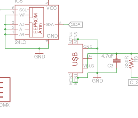
I designed the PCB using CadSoft EAGLE, I send the files away to be turned into a board.
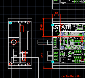
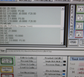
The enclosure is designed in CAD, and then I use Lazycam & Mach3 to convert the drawings into GCODE ( a set of really simple machine instructions that tell the cutting and engraving tools where to go and what to do).
The software on the unit is written in C++, and that is probably the subject of another post. I get ideas from time to time about how the interface could be developed or made easier to use from the people around me at work.
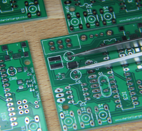
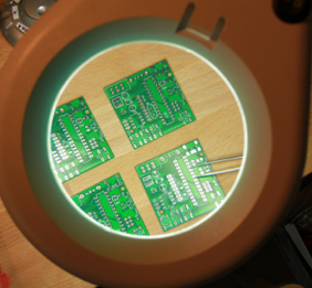
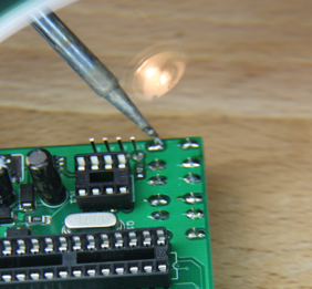
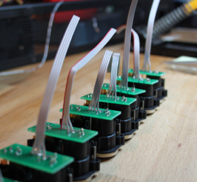
The PCBs arrive and are populated with components. I do this by hand, due to the low volume. Some of the components are are very small (<1mm ) so some concentration and a magnifying glass is needed. I use solder paste and a small tipped soldering iron and work on a number of boards at once, placing each part across the whole batch.
First stage of testing is completed at this to check voltages and battery charging operation are OK.
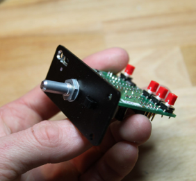
The encoder side panels go into the CNC machine to be cut. I do these first so that the assembled PCBs can be then attached to them while other things are happening, like adding the red switch caps and the OLED screen.
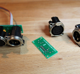
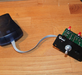
The XLR backplane is soldered up, this has a little bit of ribbon cable that needs a crimp header crimping onto it that connects it to the main board
The XLR end panels go in for CNC milling. I usually do these in batches as it is quicker to set the machine up once and then just keep feeding it material. 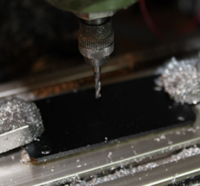
Each panel takes about 5 mins to cut. The XLRs are then screwed into the panel.
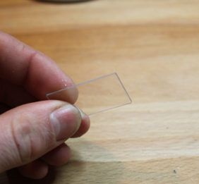
The polycarbonate windows are milled in the same machine. Due to the thickness of the material they are done one at a time, any more the warping caused by the clamps mean that the final size of window is not accurate enough.
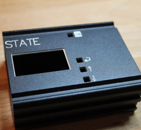
The main body of the tester is now milled. All the square holes are cut first and the 1mm recess for the window. Then it is time to change for the engraving tool and the engraving is done.
While the machine is working hard cutting holes the PCBs go over to have their processor fitted and flashed with software. At this stage I modify the line in the code that sets the customers name on the splash screen. Spelling of the name is not my strong point, so this needs to be checked at least twice!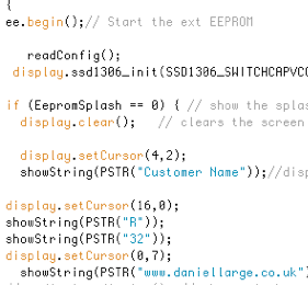
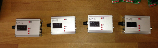
The windows are snapped into the main body and the whole unit is assembled, adding the LiPo battery and encoder knob.
Testing
Once the unit is totally assembled I then walk it through some function tests, checking that all the buttons move ok and do what they are supposed to do. I then check is the unit outputs DMX within spec, and receives DMX ok. MIDI is checked against an MSC output from Qlab. The last step is to verify that LTC functions correctly by plugging the unit into a timecode generator. 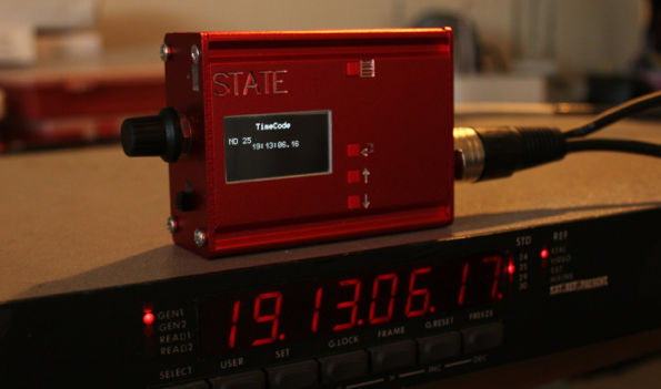
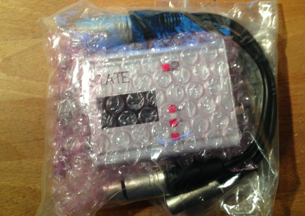
The last stage is to print the manual, and then check everything into the postbag, making sure not to forget the little purple bag or LTC/MIDI adaptor.
.