I have spent many years of my life hauling up and down a bunch of cables taping them together. When not talking toss to the person working with me, and probably around hour 2 I start to wonder why there is not some machine to help with this work. And then I go back to pacing up and down as it is actually quite satisfying.
Even a trolley with in-feed and out-feed rollers would help take the strain off. And then I thought, if you are going to do that, you might as well go a little bit further and make it auto tape… and that is more fun. So I started there. It is also fun to experiment a bit more with Fusion360 spur gear generator, steppers etc.
The scissor arm is moved by a stepper motor on the back, with a 3D printed 1/4 gear.
It is made from surplus parts and materials scavenged from around the workshop. The limit switches are from an old toaster. The scissor arm is a bit of din-rail. The mounting plate is from a failed pencil lampshade, providing lots of handy holes for clipping cables.
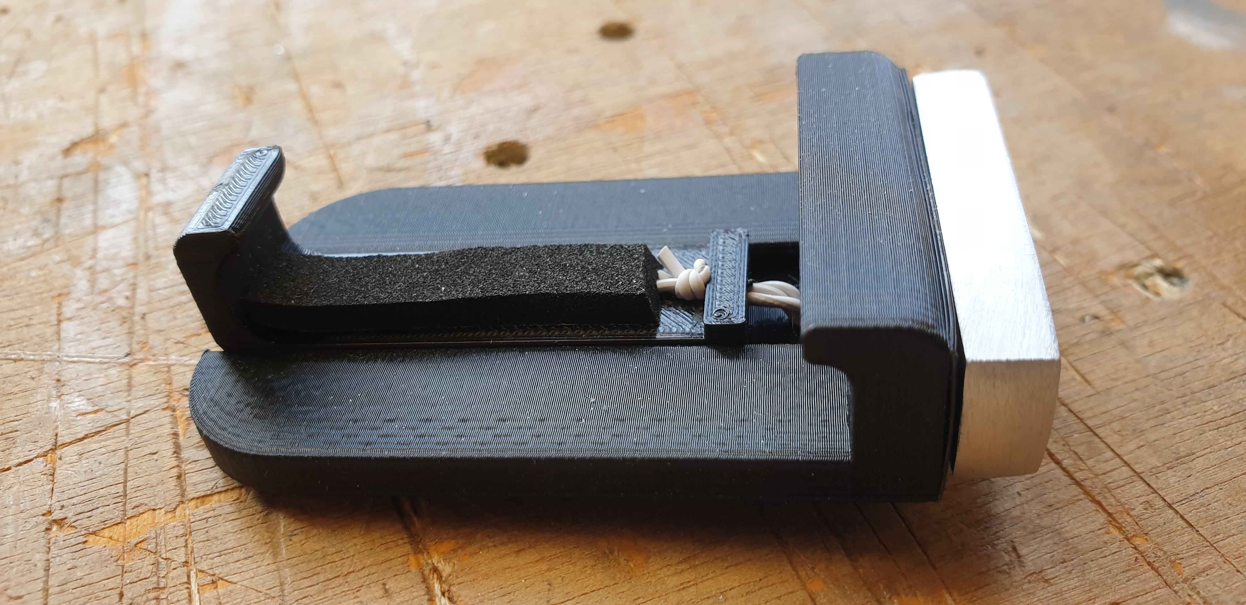
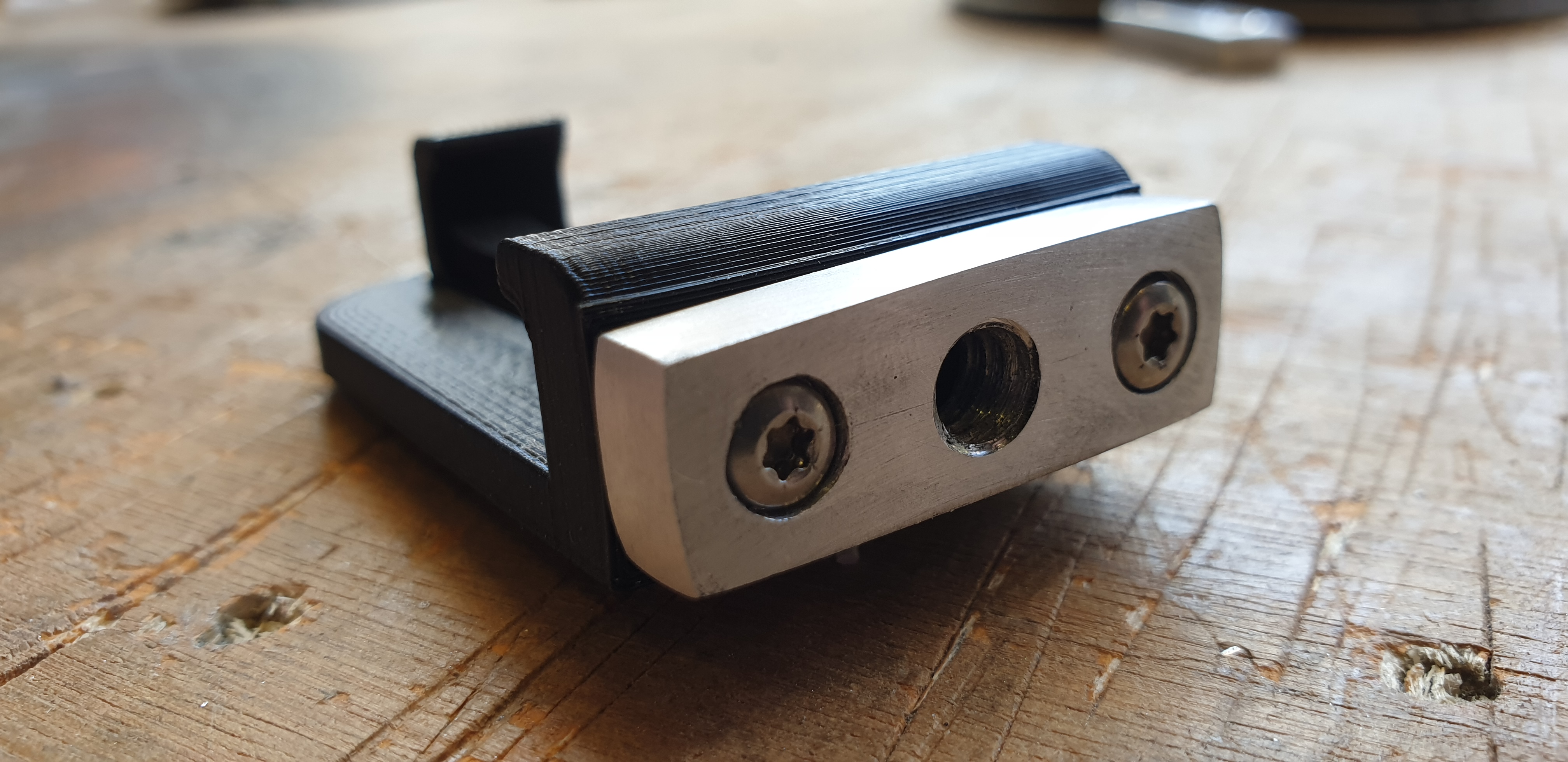
I am sure you can buy these on Amazon… This is just two 3D printed parts, and some elastic bands. Now that a good proportion of the week is spend on video calls it seems the right time to make something to adapt a phone to a mini magic arm. The aluminium bit has a 1/4″ 20 thread.
So if you read my post about Node Red and OLA, then you might have been asking yourself.. what is the point.
Heres a point!
I am building/have built/will build LED drivers and I need to asses and work on the dimming curve on them. I can do this with my eyes, but when you are dealing with 16bit values and trying to get a most excellent linear response as a starting point, it is allot of leg work. (And typing..)
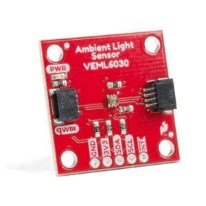
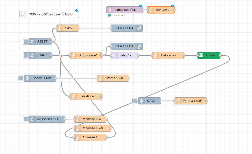
So now I have Node Red driving DMX, which is turning on a bit of LED tape via my driver, and then getting back a lux value from this sensor that I have jammed on top of the tape with a bit of make it dark cardboard… The resolution of this sensor when stuck on in this way is pretty amazing, it returns a 16bit value, and I can see a light level change between 655200 and 655201….
Enter the gsheet node, which allows you to send out data to a gsheet. Its the one in the green on the right. It deals with all the auth you have to do to write into a spread sheet remotely without having to resort to a Google Form, which is a serious tedious process.
With this arrangement I can hit go, and the thing will increment up the steps of output while taking a reading each time and banging them into my sheet. Push that into a graph and I can see just how awful my curve is…. and then start mangling the numbers to make it better. When I want to test again I just hit go and it runs the measurements while I think about how bad the curve was last time.
The google API has a limit of 100 calls in 100 seconds. So that means I can only go with a delay between increases in DMX level of 1 second. Increasing by 100 points each time took 11 mins. But that wasn’t quite enough resolution, so I am currently re running a bit of it increasing by 1 point every one second… which is more than enough time for me to write this……
A while back I had the need to make a DMX recorder that could run multiple streams of DMX and playback with a variety of different inputs. With that being the challenge, I did some learning about some pretty flexible and interesting software projects that are out there to help you a long the way.
Most people reading here will be interested in lighting technology so I am going to phrase this in that direction, but the principles of node-red can be applied to so many things it is impossible to mention, the links above should give you the resources you need. Most things can be done without resorting to hardcore code writing, and therein lies the real excitement of these two tools.
Both these things require a bit of reading to understand, and I can’t do them justice at all, so I’m going to give you a super brief birds eye view and point to some other reading.
“The Open Lighting Architecture is a framework for lighting control information. It supports a range of protocols and over a dozen USB devices. It can run as a standalone service, which is useful for converting signals between protocols, or alternatively using the OLA API, it can be used as the backend for lighting control software. OLA runs on many different platforms including ARM, which makes it a perfect fit for low cost Ethernet to DMX gateways.”
I have been resistant to using this open source platform as I generally prefer to spin my own code for doing input and output of lighting data. However for a project like this, why spend hours perfecting the reception of sACN or using that DMX dongle you have lying about when these people have created a very clever demon that can essentially gather DMX via pretty much any means, and output it via the same.
You can install OLA on a linux system, or a Mac etc, I have tried both, my linux skills are pretty crappy, and I found that using a RaspberryPi with a standard image the easiest way to install it without a degree in computer science was just use one of their prebuilt packages, installed with sudo apt-get install ola.
Once you have installed the OLA platform you can have a look at its GUI using a web browser, if you have installed it locally you can do 127.0.0.1:9090
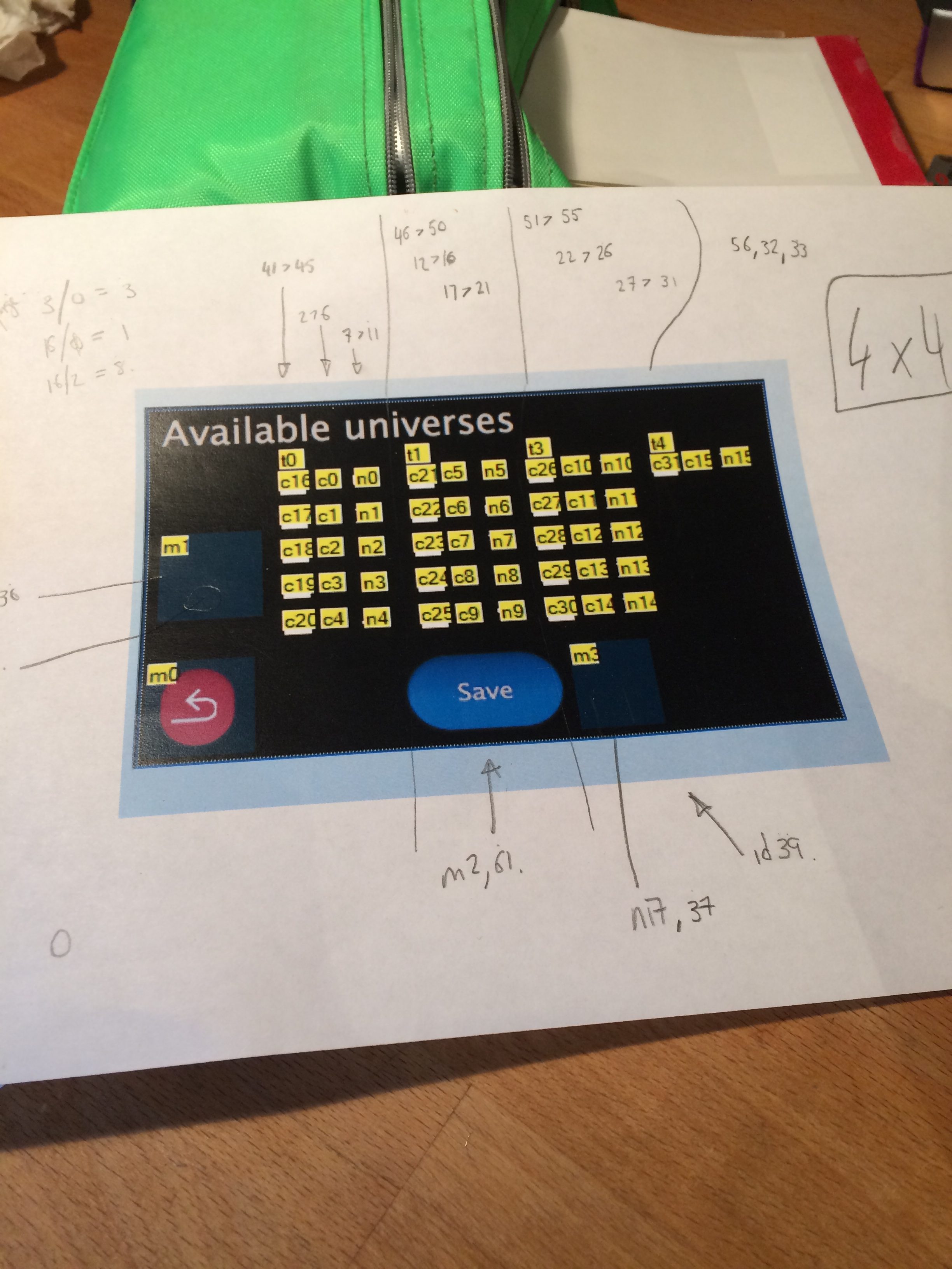
Here you are going to play with creating input and output universes, I was pretty frustrated by the lack of universe cross patch , for example connecting ArtNET 1 to sACN 10 is not possible, it only really does 1:1.
HOWEVER…
Way more interesting is if you setup some output universes you can now do good stuff from the command line.
such as ola_set_dmx–universe <universe> –dmx <values>
Entering ola_set_dmx -u 1 – d 255,255,255 will set the first three channels in whatever you have configured to be universe one to be at full.
Now then, why is that good. Well, you can now personally output sACN, ArtNET, DMX from all sorts of dongles etc etc etc from that one line. If your like me your thinking, ok great but now I have to write some code to actually do something useful with that. YAWN. Standby for part 2 – NodeRed …. just before we get there though, let’s just checkout ola_recorder. Now that is interesting, you can record and playback universes from the command line.
I tested it out using LumiNet monitor pushing in some ArtNET and then sending it back out again. It works!
“Node-RED is a programming tool for wiring together hardware devices, APIs and online services in new and interesting ways.
It provides a browser-based editor that makes it easy to wire together flows using the wide range of nodes in the palette that can be deployed to its runtime in a single-click”
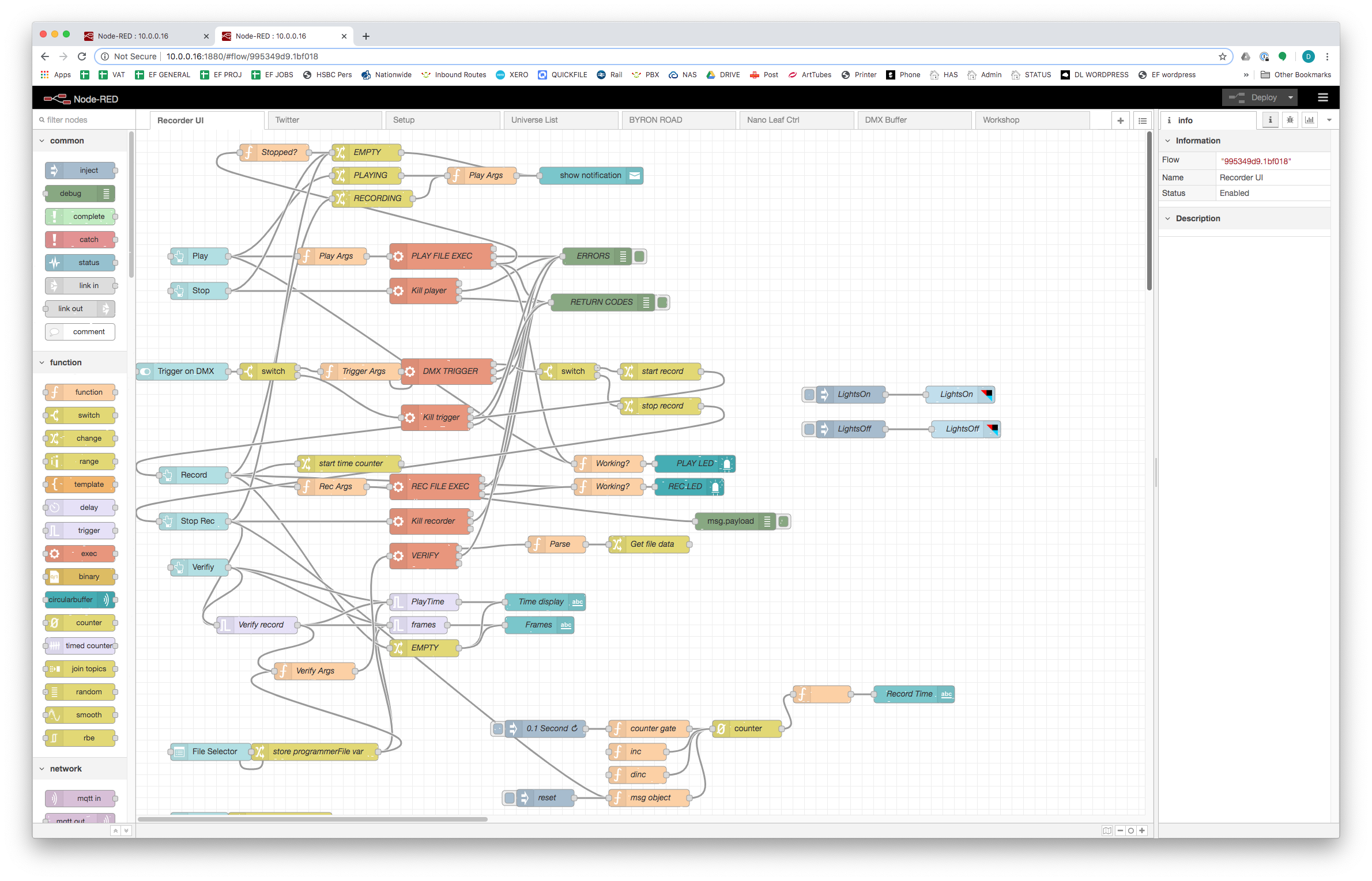
Ok so that says it all really, in the picture that the top of this post you can see my efforts at using NR to do something interesting.
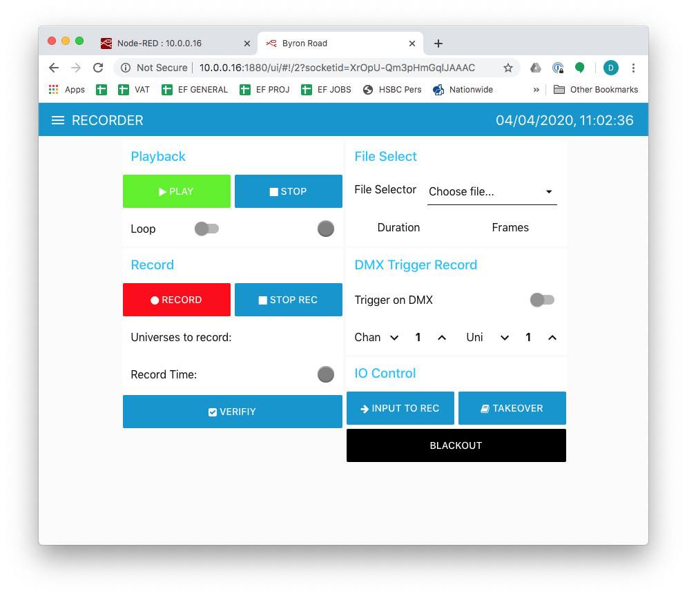
Installing node red can be done with the sudo apt-get, but best to follow their instructions. Once you have done that, you can access its node based editor with the computer ip:1880 just like OLA. There is a world of stuff you can do here, including using the ui nodes to make a really easy webserver, and suddenly you have a dashboard with buttons that can do things in just a few mins.
I hit jackpot when I realised you can install node red on the same machine as OLA, and then interact with it as if you were typing on the command line. So suddenly instead of typing set_dmx, I can have a button on the webpage that does it. Or operates the recorder functions.
Using the node red dashboard to interface with OLA
The above was a product of several days of wibbeling about trying to understand how the flows work in NR, and fiddling about to get it to do what I wanted to do.
So there we go, I would recommend having a look at both the different bits of software, and especially having a go at Node Red and seeing what it can do for you. I realise there are a tonne of other options for doing these things in a more efficient way, but for someone like me who is not super proficient in the more higher level languages it is really worth spending some time getting to know these things.
Also check out PM2 if you are feeling like running this stuff on a Pi of similar for a large amount of time, it manages processes, restarting if necessary, deals with starting things on boot up etc.
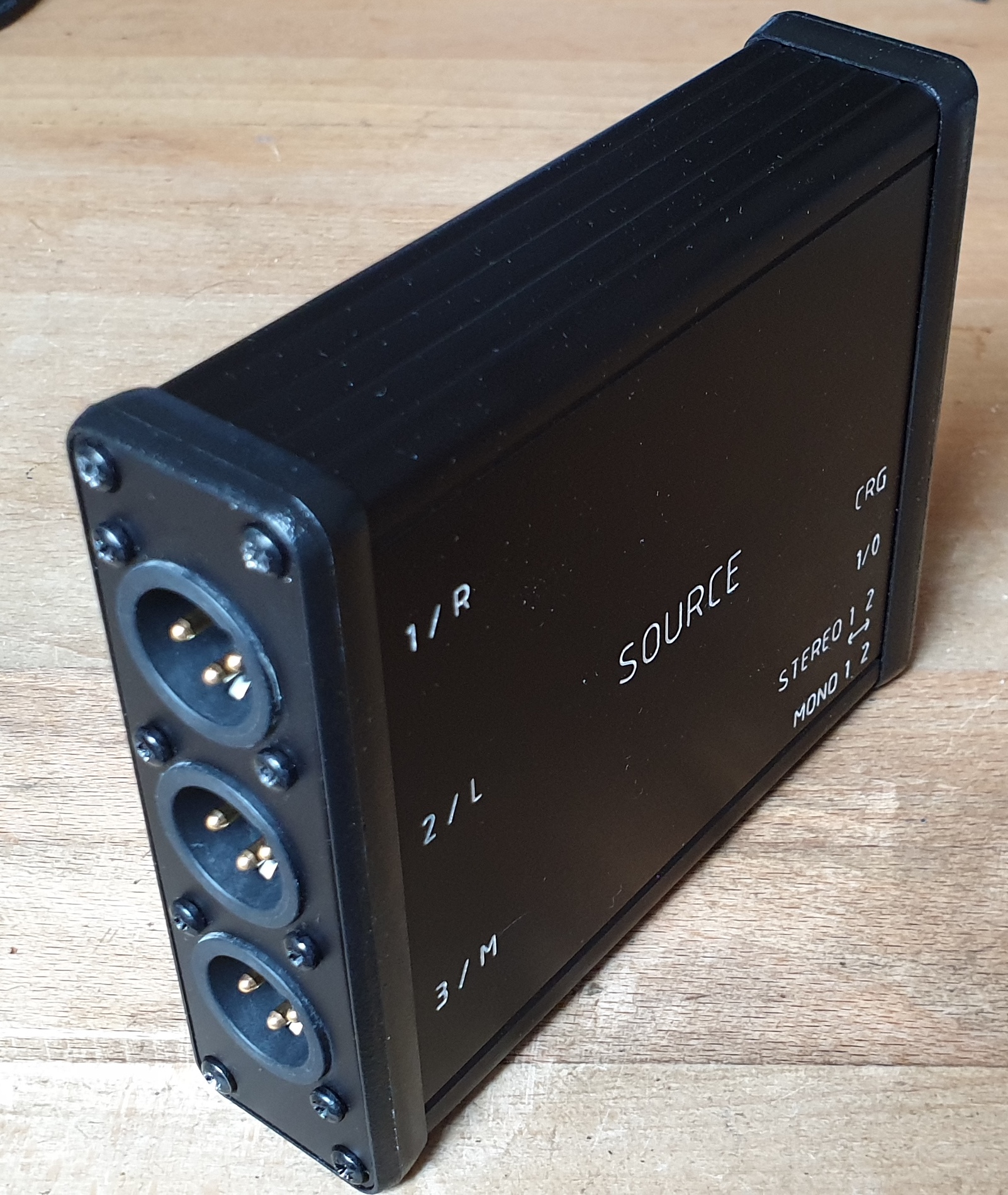
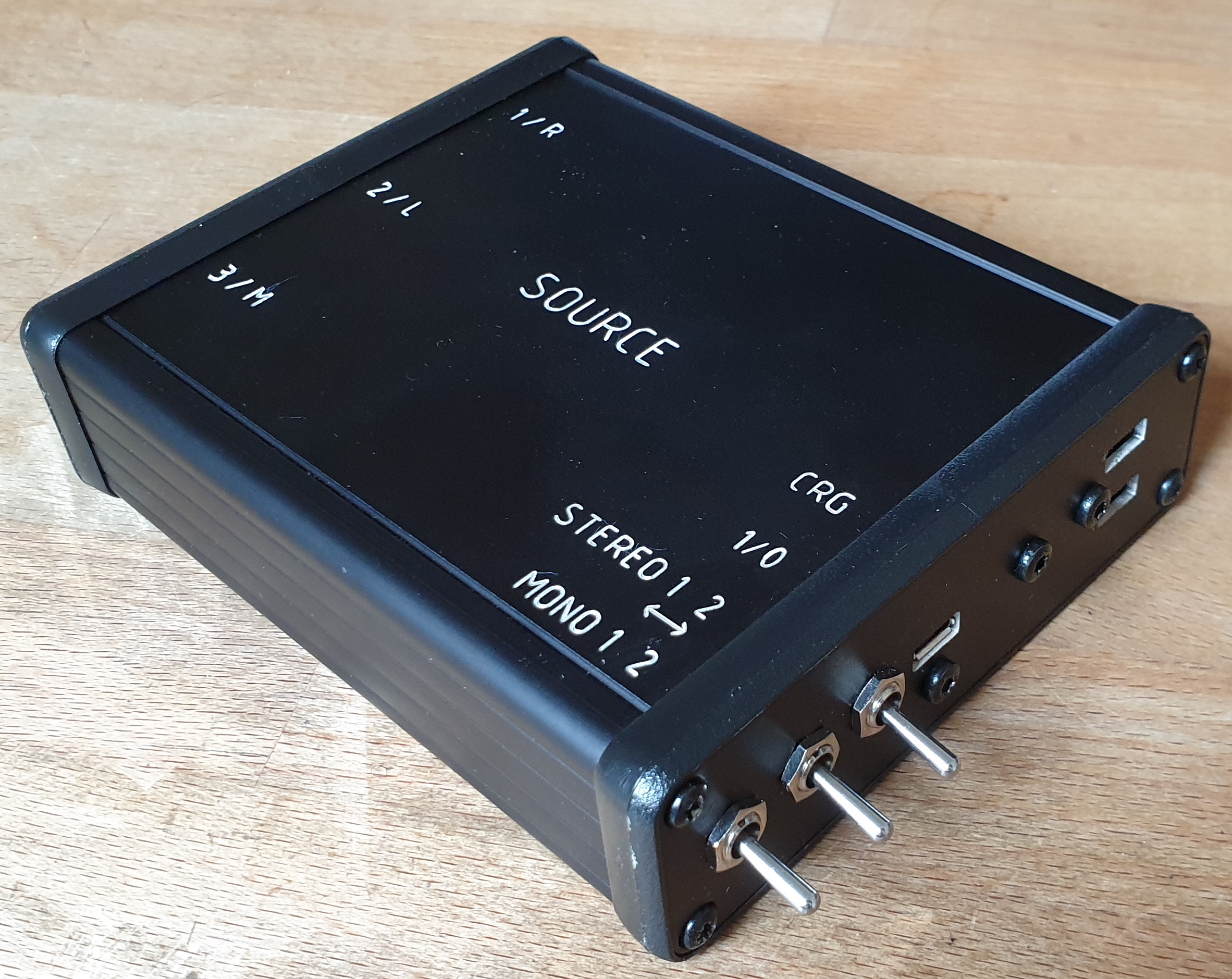
At the moment I have to check three audio related things daily – so I made this box to spit out LTC and Left and Right ident tones.
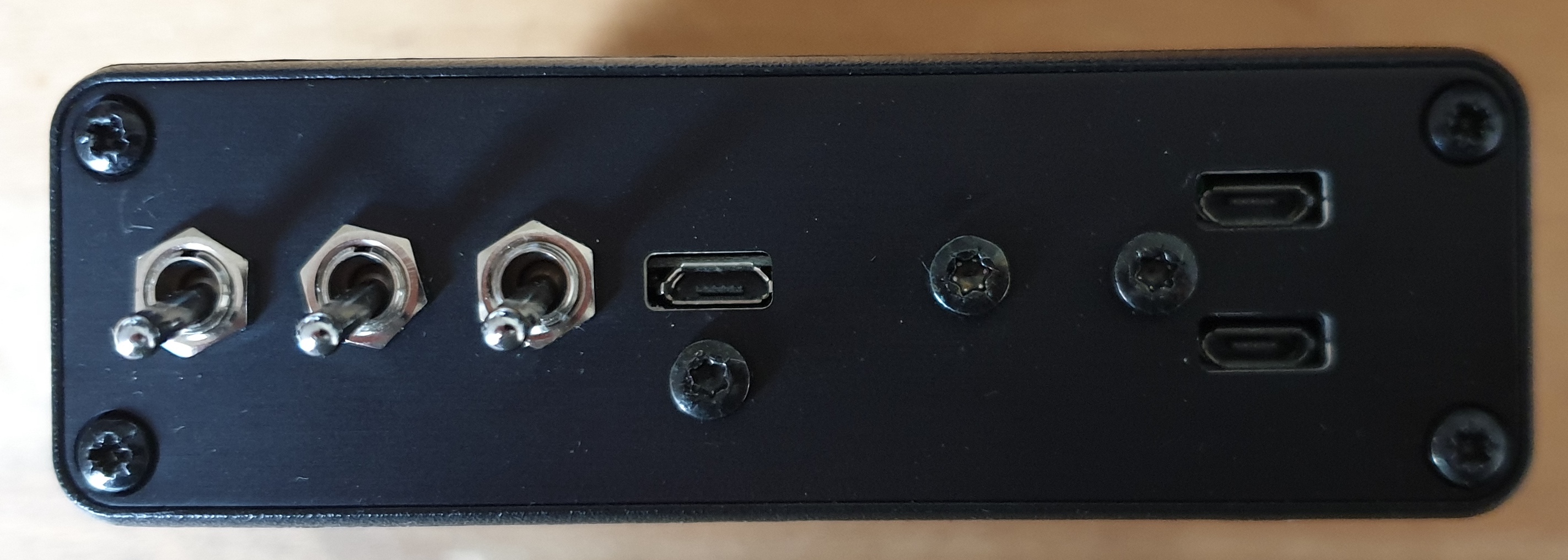
It is super simple, inside has two MP3 player modules, a battery charger and lipo battery, and some balancing transformers. The switches let you play two different files depending on their position.
One MP3 player does the stereo pair, the other the mono. So at the moment LTC comes out of the mono output and a left/right ident tone comes out of the L and R outputs. This helps me check that everything is plugged in the correct way around all the way through the various snakes and crossovers to be received at my rack. You can load files with the USB sockets on the right, and the unit is charged with the socket in the centre.
It could be useful for building up racks when you just need to insert a bit of timecode and check it is getting to everything, or audio is getting to all your recorders etc.
I am on tour at the moment, so not much work on STATUS, however I thought I would share this box I have made to make life a bit easier.
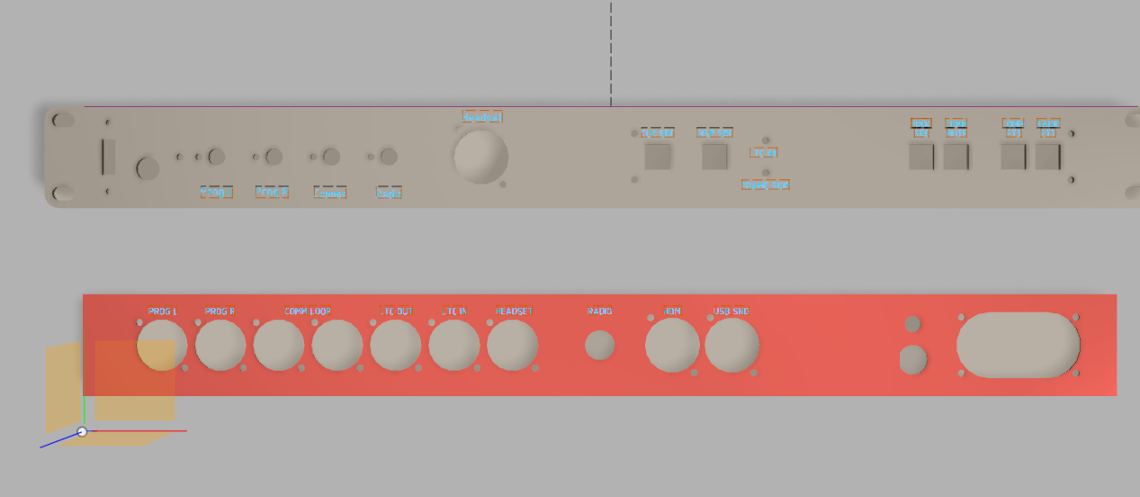
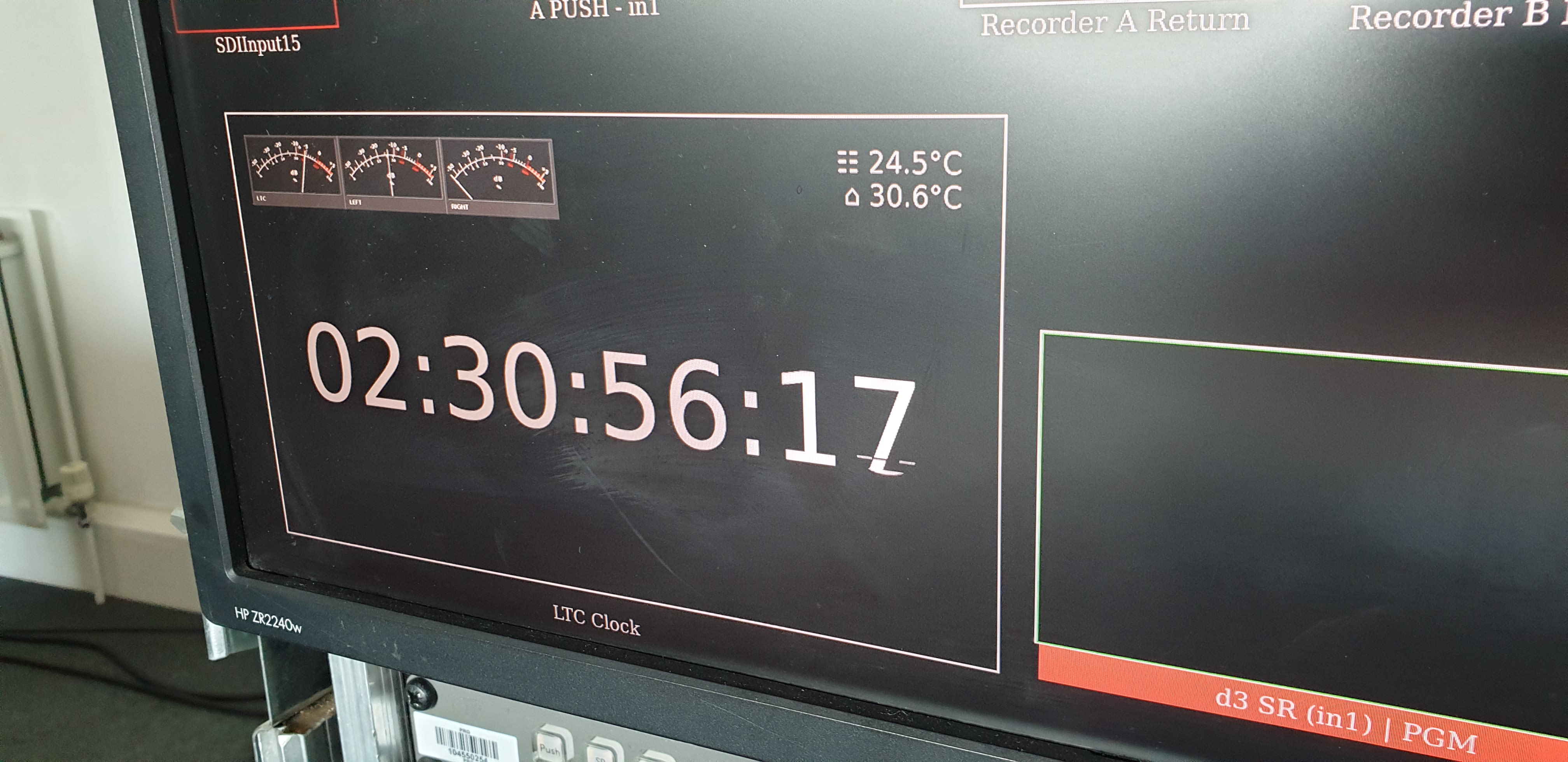
The main goal was to output a LTC clock via HDMI so I can burn it in to recordings, however feature creep led it to include some audio meters, and then included some comms requirement. It is a bit particular to my setup, but I crossed some interesting bridges along the way.
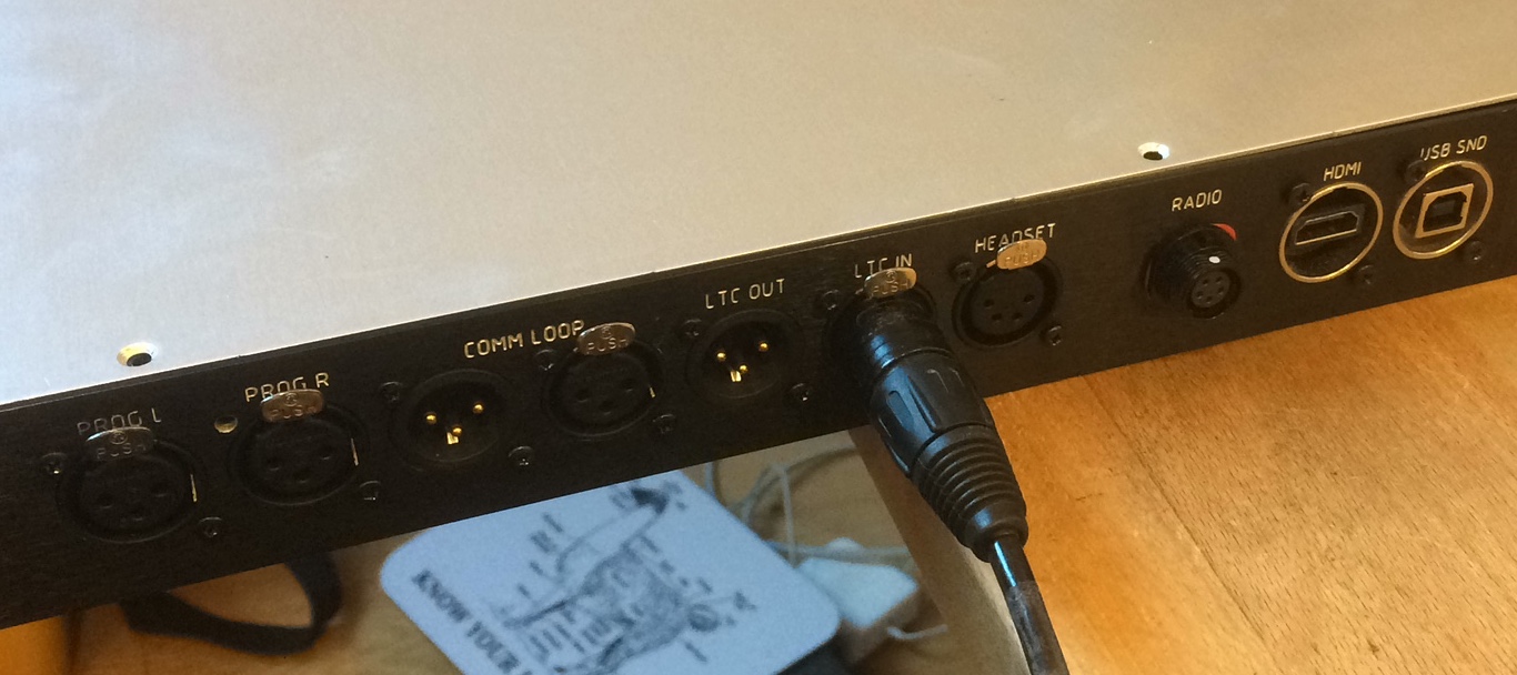
Inputs – LTC, 2Wire, Left and Right program, Motorola Radio, USB sound (LTC left, program right). Tempreature probe x2. Headset mic input.
Outputs – HDMI (clock), Headphones, Headset, LTC.
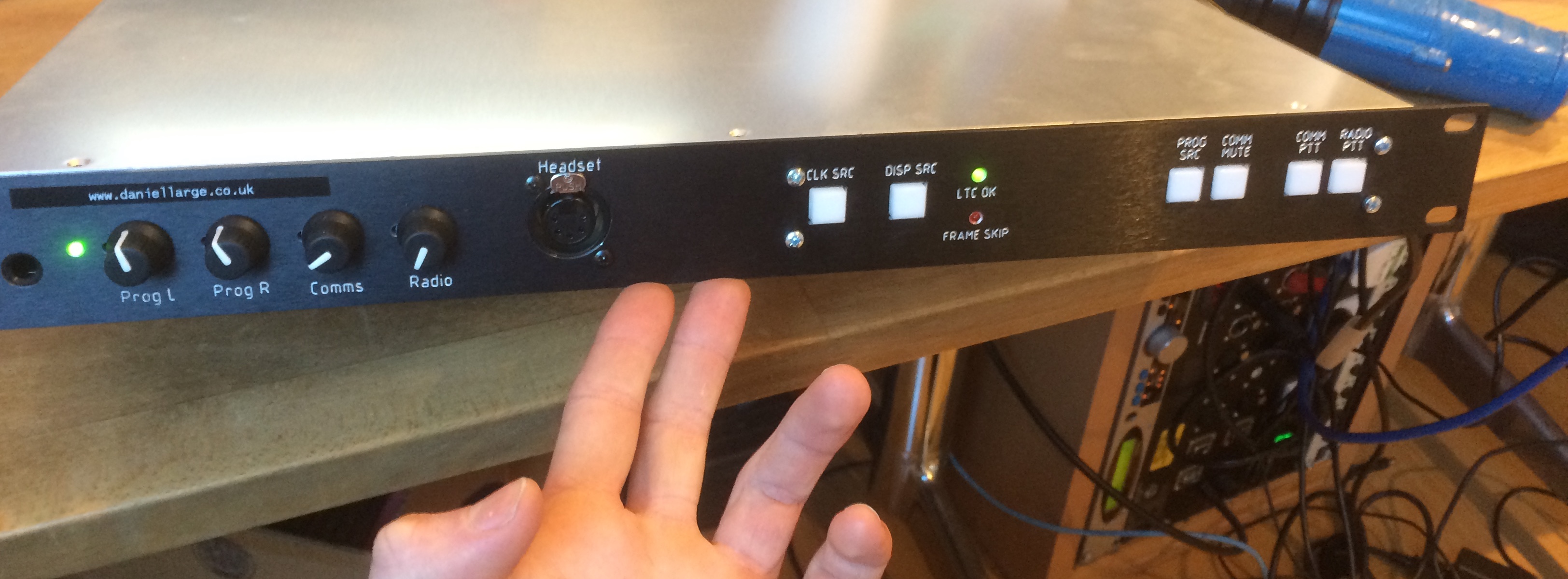
Comms, radio and program are mixed via the knobs on the left into the headset/headphones.
The headset mic goes out to 2wire coms circuit or to the radio when the push to talk switches are pushed.
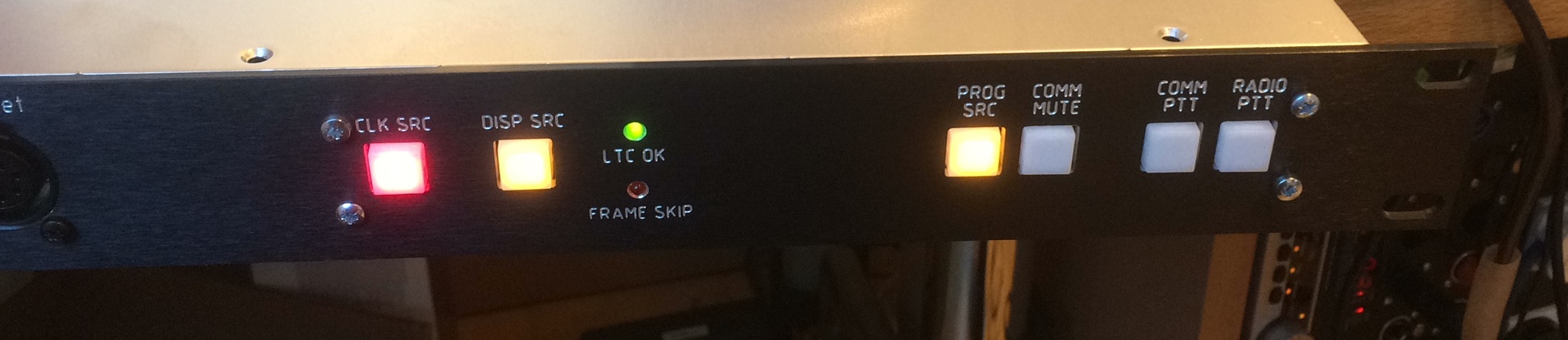
The LTC input is displayed on the clock, hitting CLK SRC flips the LTC input over to a rehearsal setup where the clock is input to the rig via the USB input, so you can take code from the show source during normal operation, or changeover to outputing from a laptop when in rehearsal mode. The LTC OK and FRAME skip lights indicate if the LTC is in spec. If you have an intermittent/quiet/loud input then the frame skip light goes crazy.
The DISP SRC button let you switch the reader element from USB or show source. I use the CLK SRC button in show situation to disengage the media servers from the LTC line – it flashes red which is a good clear indication.
Construction: Not for mass-production. There is a reason why there isn’t a picture of the inside. It contains half a mixer, a Behringer sound card, a StarTech sound card, two custom PCBs for connectors, signal switching and isolation (one with a uC on it to do the button and LED logic) a raspberryPi3 for LTC decoding and HDMI output. Some power supplies and a mic preamp. Quite allot to pack into a small space. If I were to make it again I would attempt to roll my own soundcard and mixer.
A few people have been asking me to make them socca flash out boxes, socca grenades, etc etc. It looks like it is becoming hard to get the really nice GDS one.
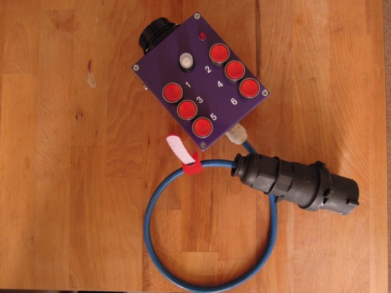
I made the one in the picture (plus a couple of copies) in 2012.
I don’t really want to sell these as they cost more to make than you want to pay for them, so I am posting the plans and part list for a flash up box, so IF YOU ARE COMPETENT please feel free to use them to make your own 6 channel flash up box. OR more excitingly mod the plans, make something better!
Plans are provided as is, no warranty / help ! You are responsbile for the safe wiring, adherence to relevant local wiring codes for protection against electric shock and fire risk.
I have seen all sorts of these on my travels, some people do a rotary switch instead of 6 buttons, thats nice so you can leave the channel engaged an address a moving light for example. I like these big fat red button switches as they are really hard to smash, the think has been kicked across the stage and generally rides in the bottom of my tool box underneath my spanners without damage… plenty of scratches now!
To make my one you will need the following parts… (from CPC)
Q
CPC
Part
1
EN81987
Enclosure
1
FF01647
thermal circuit breaker
1
FF00583
breaker button cover 2 pack
6
SW04569
Switches
1
CN01655
Socca female
1
PL15610
16A Plug
1
CBBR7835
20mm Cable Gland
1
CB19619
0.5M of HO7 TRS
1
SC10655
Neon indicator
I like to drill holes by printing the dwg 1:1 and sticking over the box, and centre punching out where the drilling should go.
Be warned, there is a allot of wiring to fit in the box.
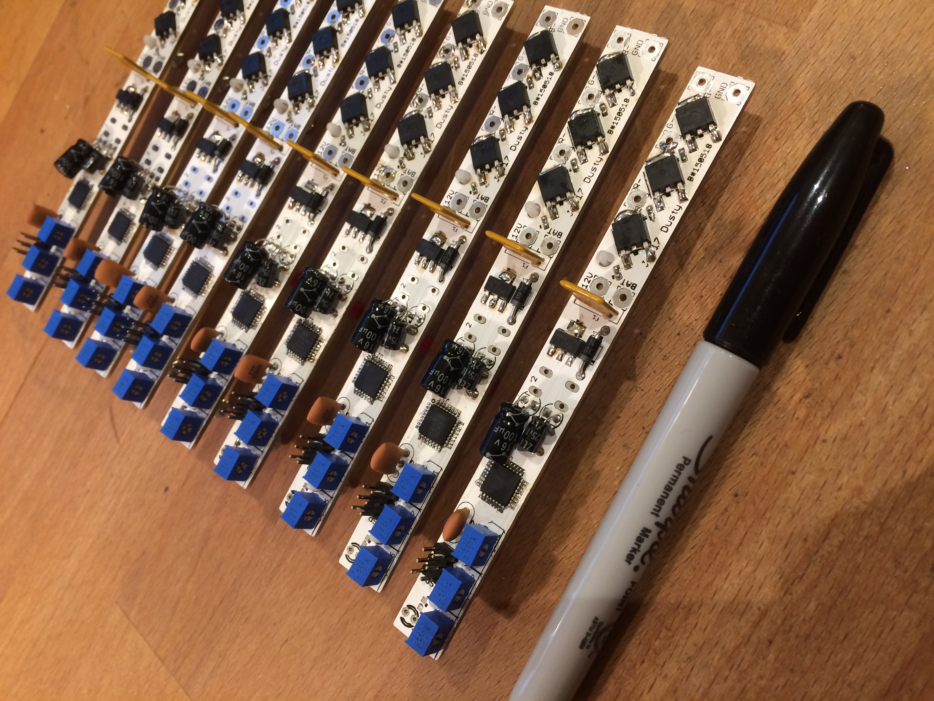
I have just finished making some LED controllers, they have a pretty simple purpose, to turn on and off some RGB LED tape, powered by batteries. There are three trimmers so you can mix the colour you want when you hit the button (on the back of the PCB). The module is long and thin so it can sit alongside the tape in 30mm wide extrusion, and the button can poke through the back.
It has a programmable processor on board so that it can be programmed to do other things, like fade, or change colour… but thats for another day.
They are for Electric Foundry – see www.electricfoundry.co.uk
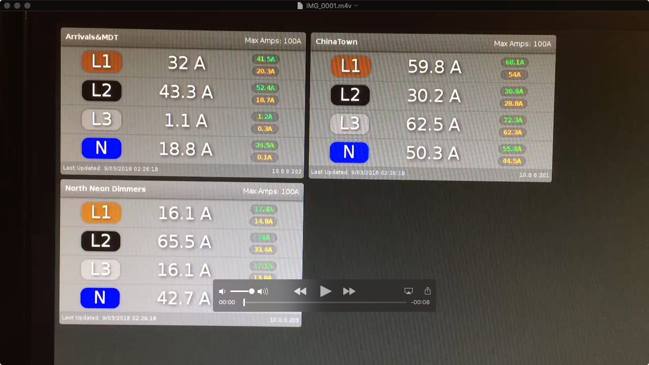
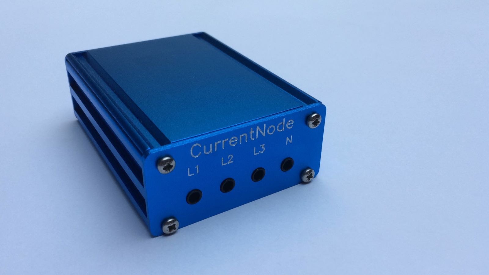
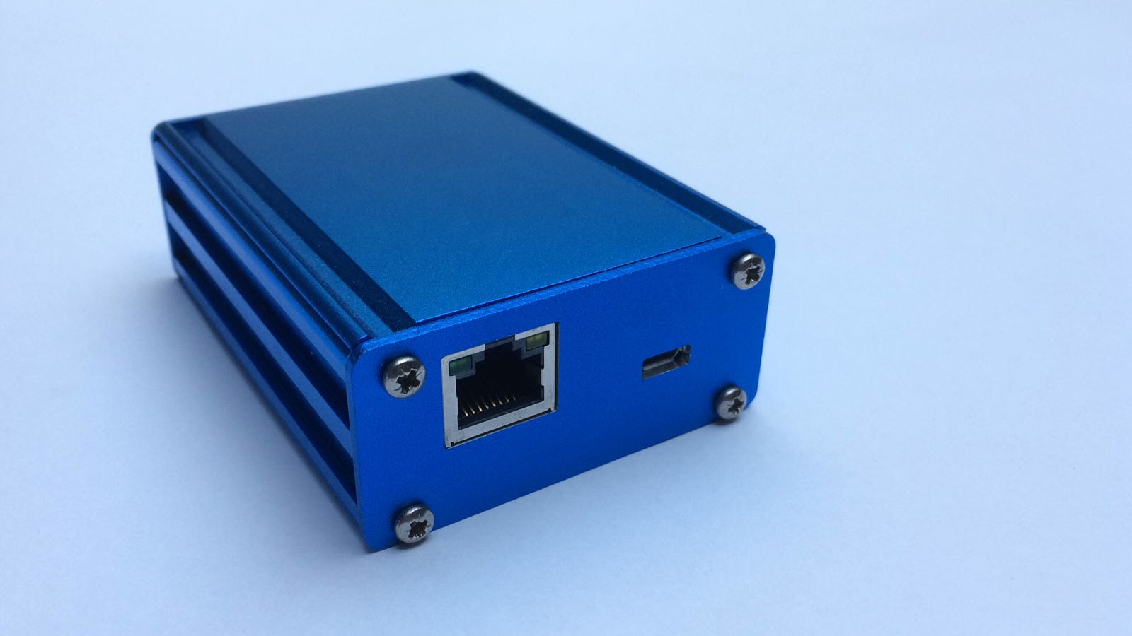
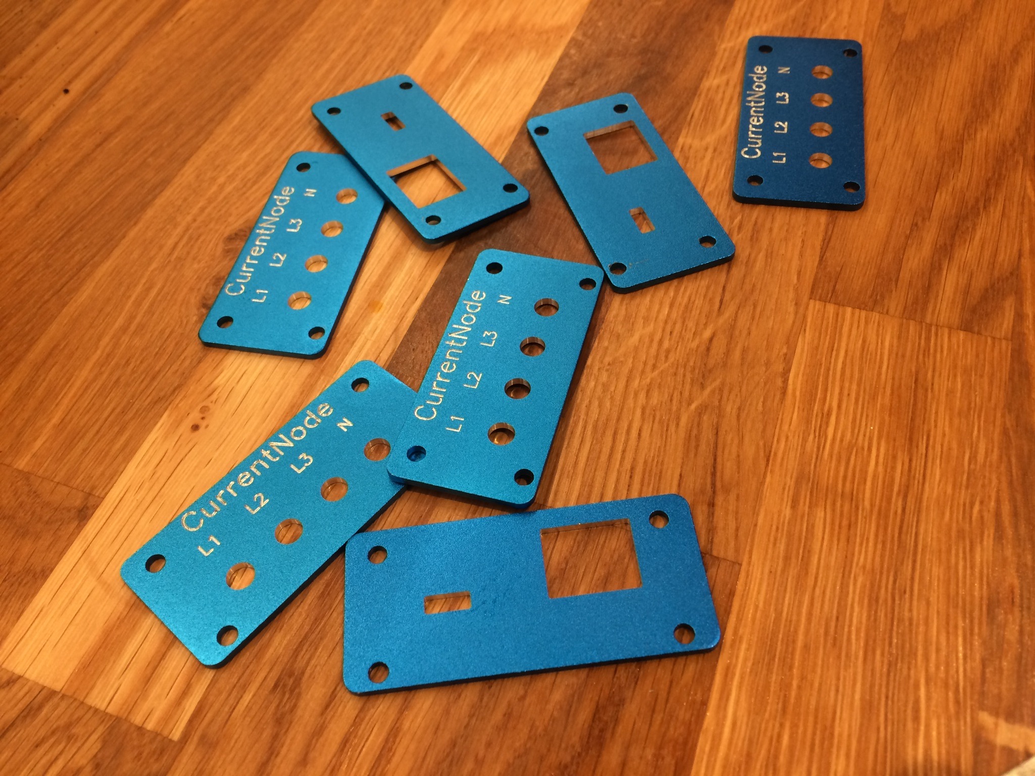
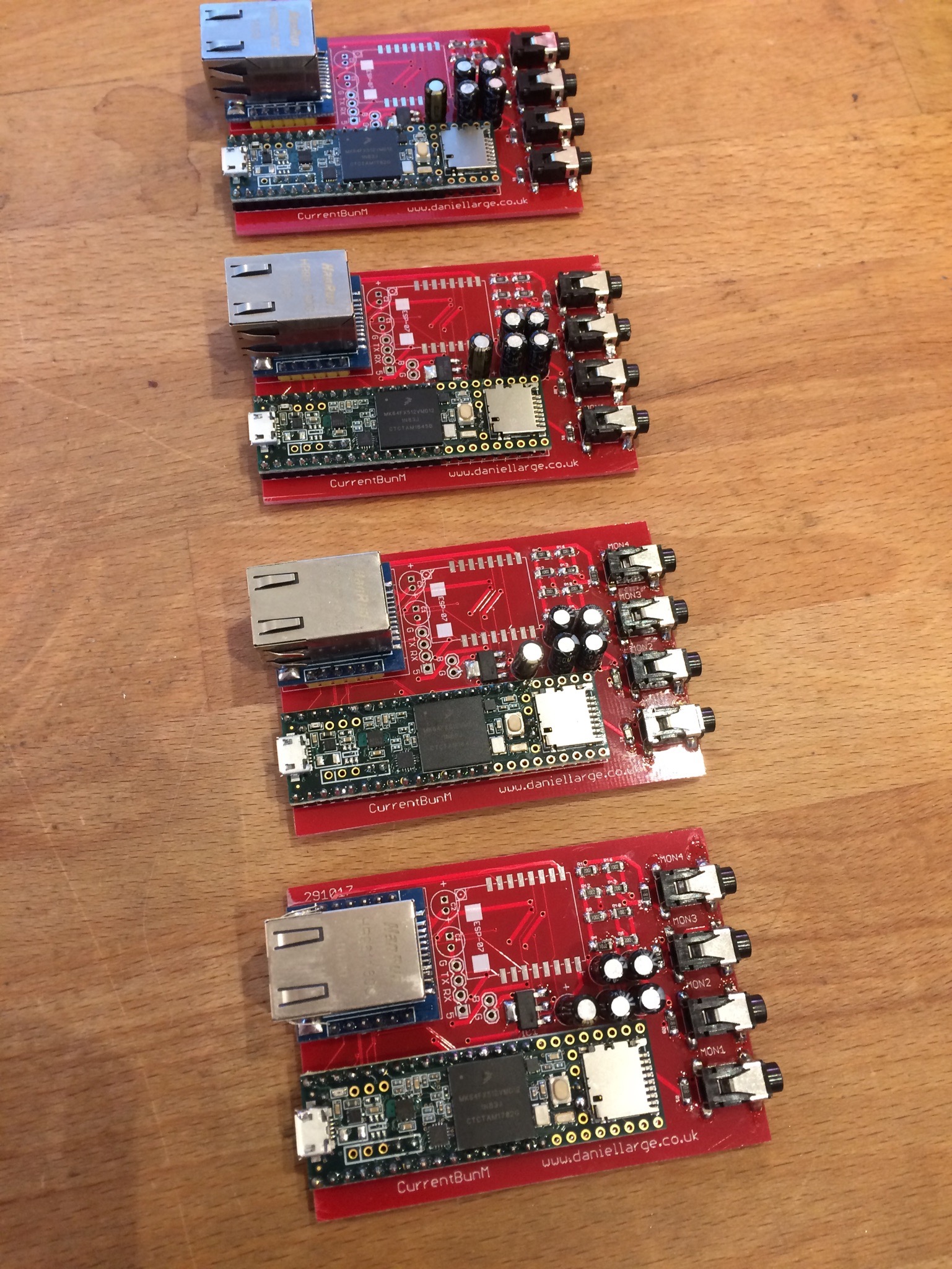
More CurrentBun news, working with a good friend of mine we have created a very simple version of CurrentBun. There is a tiny server that server a webpage up displaying your Currents. With alarms etc.
A few months ago I did a rush job to detect some footballs in very small football nets for a football boot brand, the player had to boot the ball into small holes in a wall in sequence to win. I got this working with one of my “BEAM” boxes, but modified to accept 12 laser beam break sensors, so that a invisible net could be formed just behind the hole.
It worked, but It got me thinking, what would happen if I could do it without the fuss of all those sensors and reflectors. AND what would happen if I could sense the velocity of the ball and turn that into some kind of lighting or sound buisness.
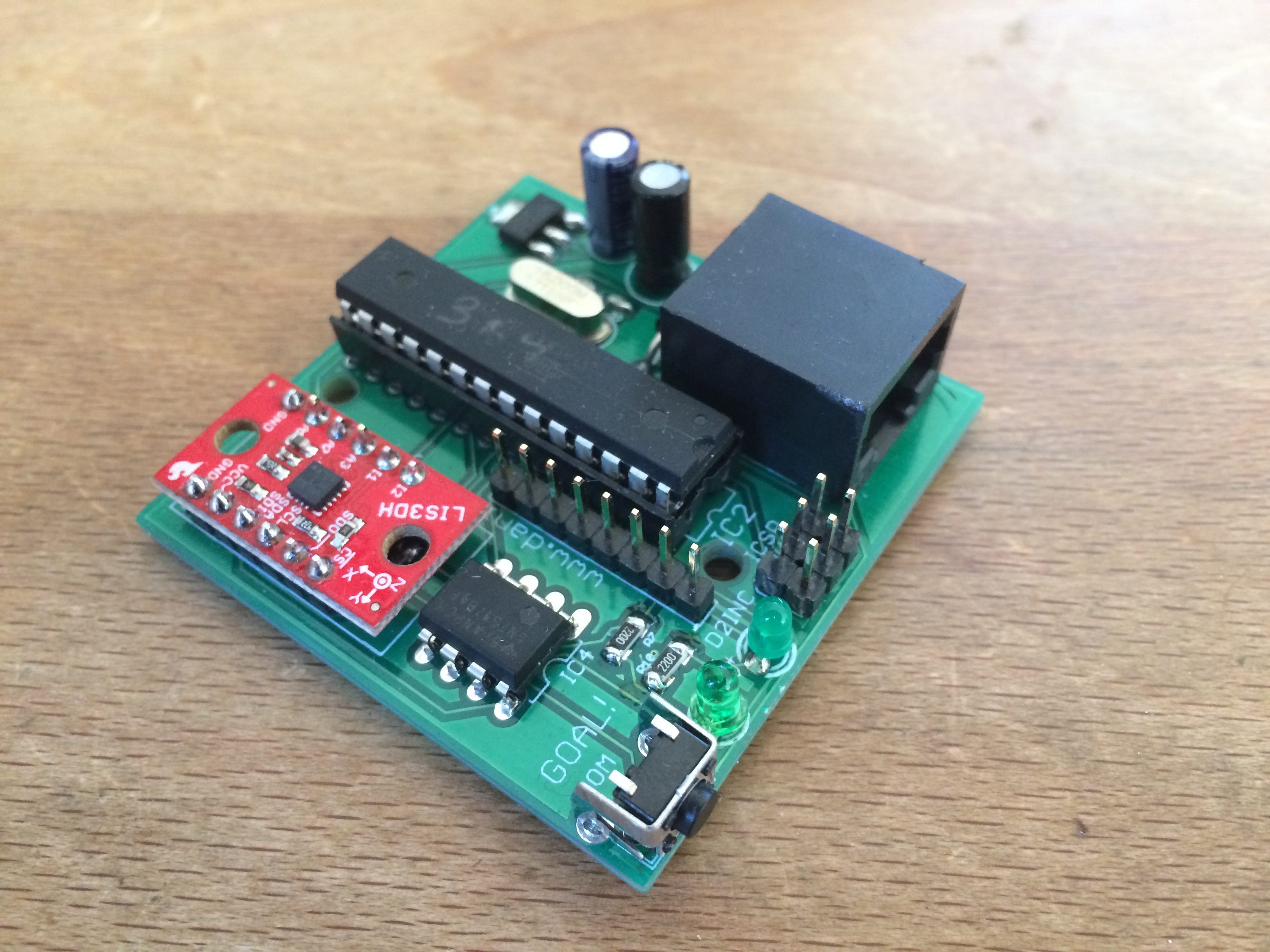
In this weeks Seeeed delivery was GOAL! a board I have deisgned to take the input from a 3 axis accelerometer and turns it directly into DMX. The DMX comes out of an RJ45 socket that also has power input on it, so it could be mounted in a speeding ball proof container and clipped to the net directly for some interesting sensing!
Some updates on the STATUS project (there will be another video soon).
I have the parts for 10 units that are going to go out to some testers before the first release. So don’t worry all you people that have asked me for one, thankyou for your support and feedback, not far away now!
RDM development coming along, usual sort of controller modes going in now.
And a special one I’d like to talk about FixPrep. This is an idea I have had while prepping too many fixtures. It uses RDM to grab a fixtures start address, footprint and mode as a template. You then connect another fixture and it auto-programs it to the same as the first, but with a start address offset by the footprint. I have put some buttons in to allow you to factory default the connected unit. Any lots of checks so that you have to connect a different fixture to go, or if you connect a new type of fixture the process stops and asks you what you want to do.
Pressing Addr lets you override the auto-address and set a new one. you don’t need to press send (it detects a fresh fixture) but you can if you want to re send for a new address.
You get a nice big green flashing tick when the fixture is programmed. And it is much faster that going through those menus! Your light has to have RDM of course…
The fixture in the pic below does not support mode names, so instead I just display the footprint info after the model name.
Fixture Prep Page
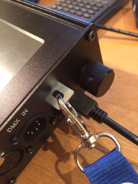
Another new one on the hardware front… Lanyard attachment point. Doubles as protecting the on off switch a bit. It is stainless steel and I have been dropping the poor thing on it all afternoon….
It has been a busy start to the year. I am working on STATUS in every spare moment. Here is a little aside. This project came in just before Christmas. The idea is that some hanging lamps need to be swung about theatrically when a storm blows in (etc), and there is no access for person on string method usually preferred. Bit of a video to go through the design and manufacture process. Not much time for RnD it was pretty much straight to the tools and hope for the best.
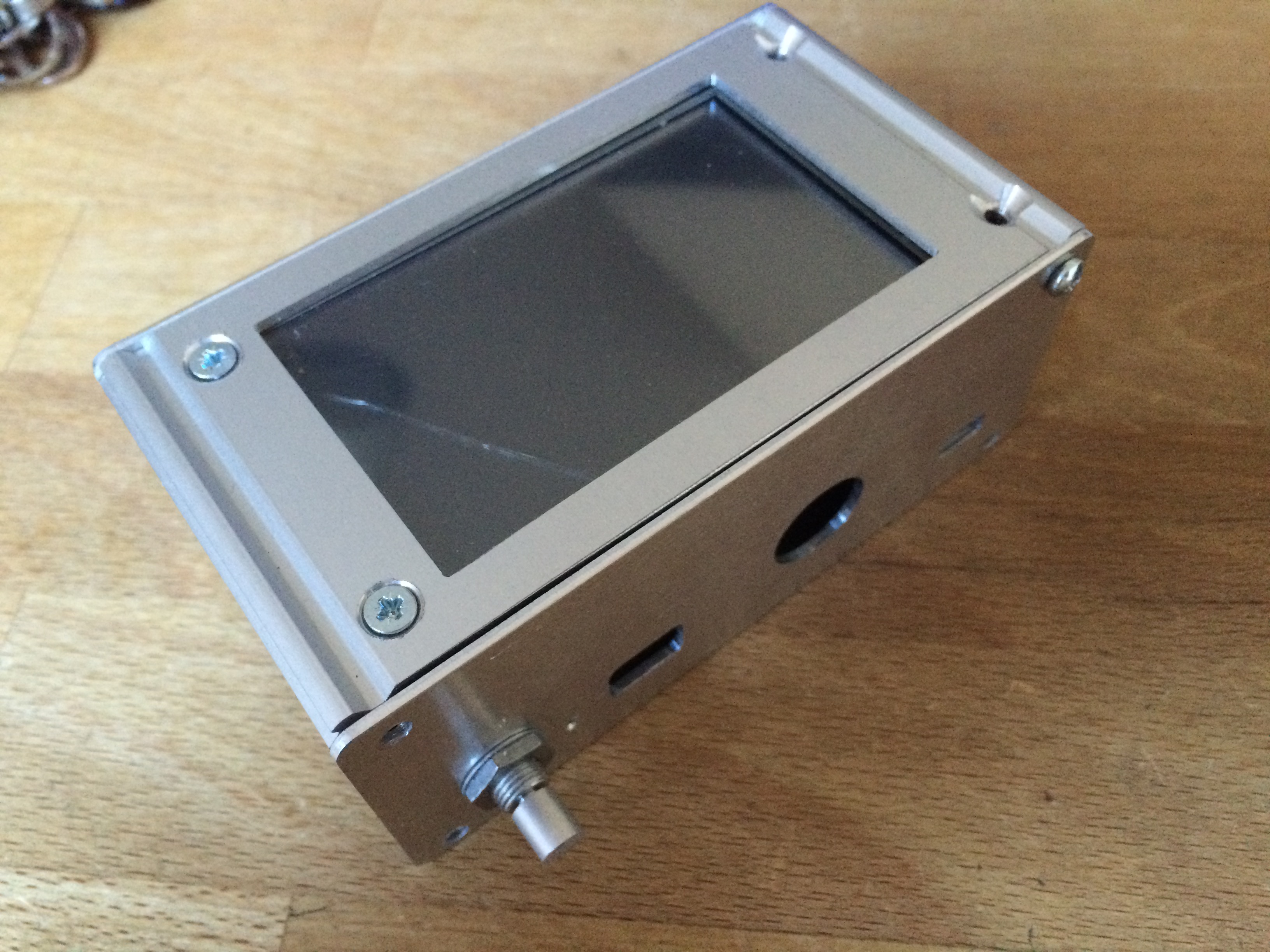
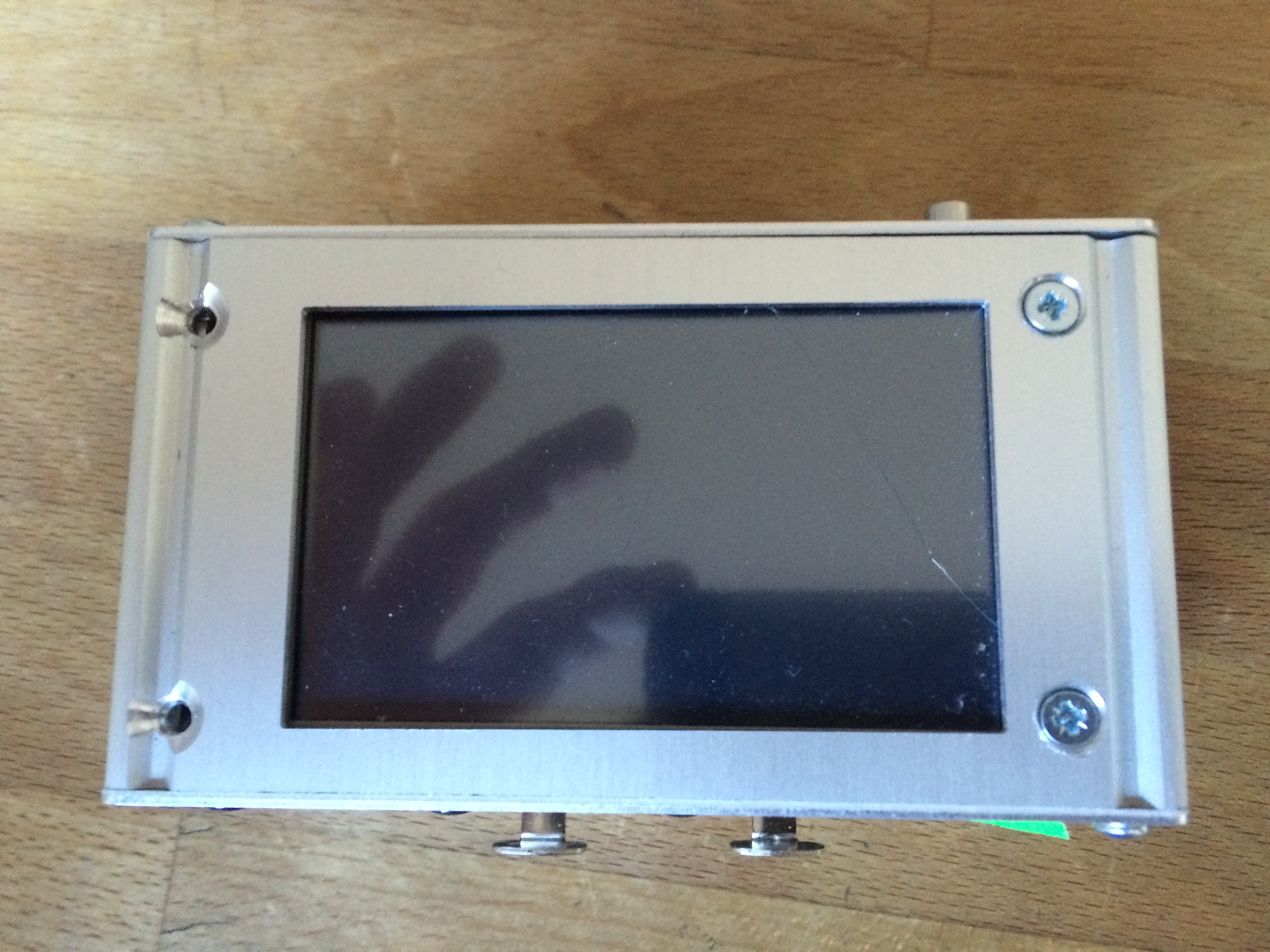
Lots of new stuff to talk about so I made a video. The case is still awaiting a bit of work, as you might be able to tell by the odd screen centring and lack of right hand end.
As usual, any suggestions or thoughts, drop me a line. Thanks very much for all your feedback so far.
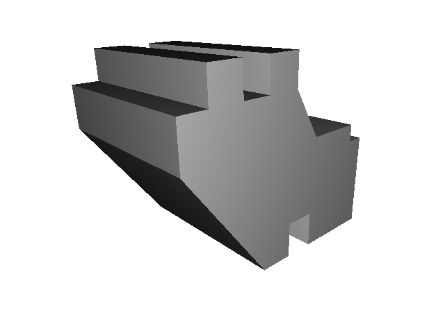
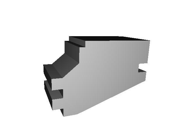
This week I have been working on mounting the STATUS touchscreen in a nice solid way to the enclosure, without fasteners. With the help of some rapid prototyping with Matt from www.mt3d.uk these are now some nicely fitting 3D printed parts that snap into the internal rails of the enclosure. It took a couple of goes (4) to get the fit perfect and the printing time down to a reasonable level.
To those in the 3D printing world this might be old news, but it is still a weird feeling to draw something in the imaginary computer world only for it to turn up the next day as a solid object.
Prototype boards are in production for the next round of improvements.
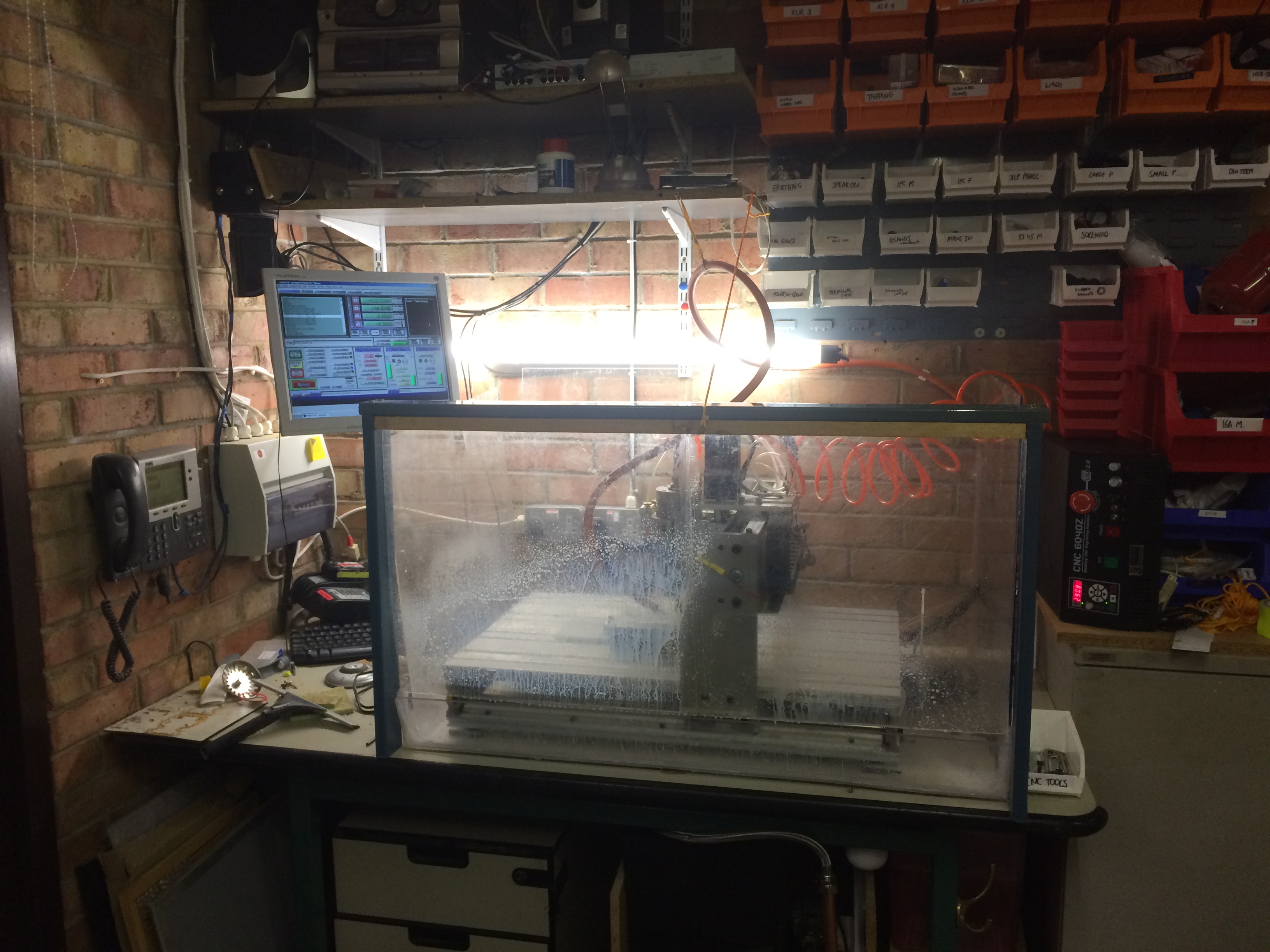
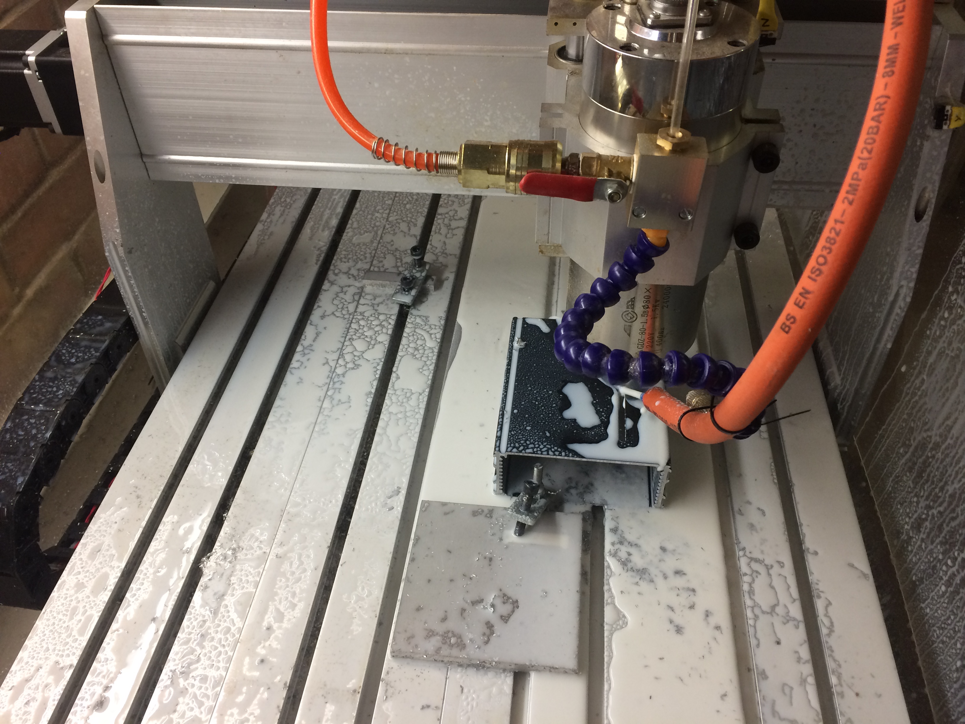
The CNC machine has had a coolant upgrade. I was having to constantly squirt WD40 onto the end mills when cutting metals, which is both a pain in the ass and probably an environmental disaster, not to mention breathing in hot WD40 fumes is I’m sure not going to increase my life span.
4 trips to Screwfix later I have a load of 22mm compression plumbing fittings, a central heating header tank and pump. Amazon has provided a ‘whole house 5 micron’ water filter to filter the small chips out. I ordered up some pre cut polycarbonate sheets to make a box/tray and stuck it all together with solvent weld. The coolant pumps onto the cutter, then drains into the tray and into a sink waste, then back into the tank. It develops a pretty decent pressure so I hope that will blow away those irritating bits of metal that get welded to the cutter.
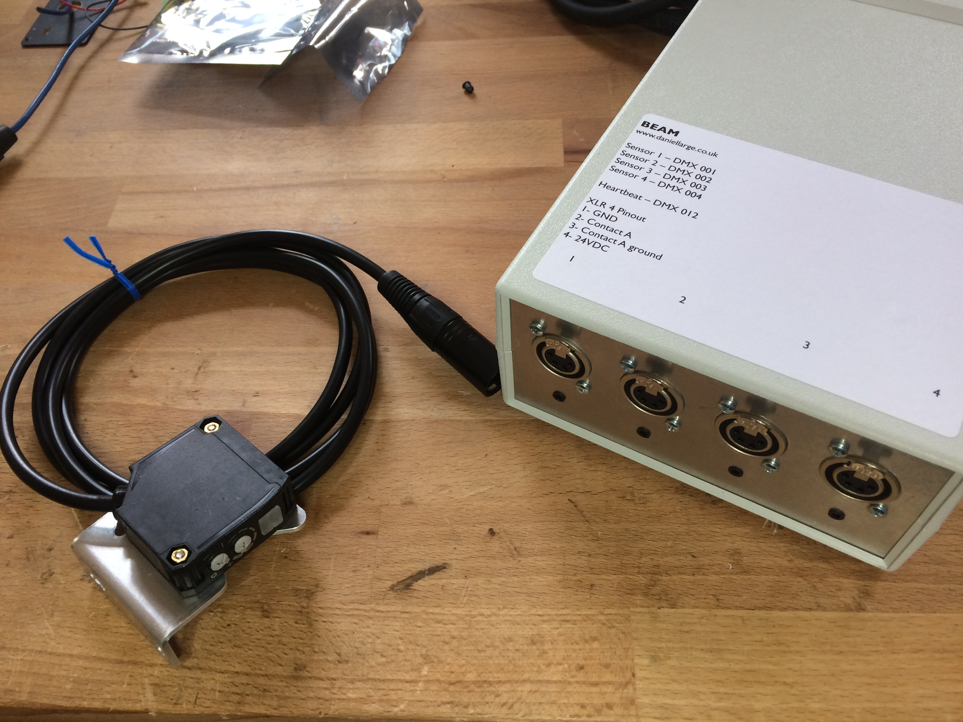
Quick project for a customer – challenge: detect people at different places in a tunnel and trigger a lighting console to do something (unspecified).
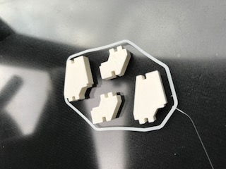
I have decided that PIR is too indiscriminate, especially if there are loads of people in there, so I have gone for some “retro reflective beam break sensors” Which are essentially a beam of light from a device that hits a mirror and comes back to the sensor on the device.
I have hooked this up to one of my EXHIBIT boards, that has plenty of in and out, and programmed it to send DMX channel 1 to full for sensor 1, 2 for 2 etc. There are 4 sensors in total. This means it can be used as a DMX Remote for the MA console the customer has, and trigger a macro or a cuestack to do whatever they want. I have added a timeout, so you don’t get a mass of triggers if a couple of sets of legs walk through the beam.
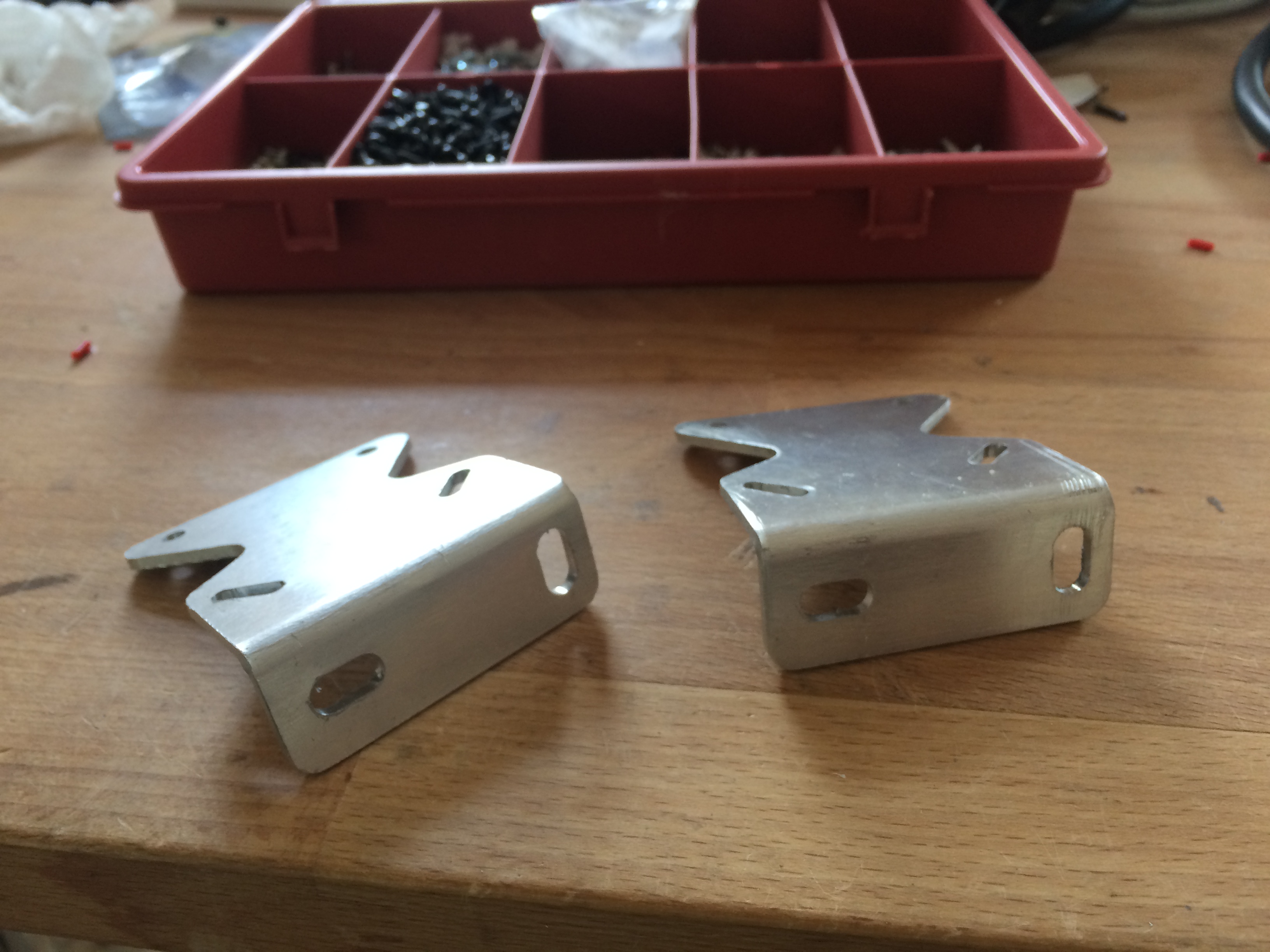
The sensors didn’t come with any brackets and as they are a bit of a fiddle to focus on the reflectors I made four of these.
And here begins my journey to RDM nirvana. I should preface this with I didn’t get that degree in electronic engineering, and my interest in this sort of stuff is that of frustrated lighting technician.I have recently had two RDM experiences, one; 30 led batterns with no interface whatsoever and a controller provided (French interface only) that would make a cup of tea better than addressing fixtures.The other was a JEM AF2 fan, that had a nasty case of random wind when connected to an EOS with RDM discovery enabled.
So here we go, how can I make a controller, and how does it work anyway.
First steps.
Most things I read about RDM is about being a responder (a fixture) There is an extremely boring spec document that specifies how to behave. With DMX you are just sending frame after frame of data, separated by breaks and stop bits, to be an RDM sender you need to be able to send stuff that isn’t DMX and then immediately stop and listen to see what comes back. All that toss about RDM compliant buffers is all to do with being able to send data both ways down a cable that you only normally send one way.
The spec shows a whole load of standard messages to send, I’m going to try a “Get Device Info” first or “E120_GET_DEVICE_INFO” because engineers love a caps lock underscore combo. The packet of data starts with a Hex 0xCC byte, if it was DMX we would send a 0x00.
Once you can send and receive you need to need to know who to talk to, and of course it can’t be via start addresses that we all know and love as the whole point is RDM is to able to mess about with them.
In the standard all fixtures that work with RDM should now have a unique ID or UID.
The first thing as a controller is to figure out who is connected to your line and what their UIDs are via “Discovery” I’m saving this for another rainy day. Today I am just trying to talk to one ELDO led driver sat on my desk, I know it has a UID of 0x64, 0x6F, 0x00, 0x00, 0x8C, 0x10 (don’t ask me how I know that)
So thanks to Open Lighting Project’s packet builder and some assistance from computer genius Peter I have worked out what I need to send to get the thing to talk back, and start sending out data and trying to listen.On my microcontroller I have a RS485 transceiver hooked up to the dmx line, and I have control of the most important pin – the REDE (receive enable send disable) when this pin is high or low puts the transceiver in a state of listen or send.
Here is me sending out the get info packet , the left blob is the data going out, and on the right is the ELDO talking back… or in this case, the line is still being biased by the controller so it is just causing a load of noise on the line. I checked this by sending data with the ELDO unplugged and I didn’t get the right hand blob.
Now I’m flipping that REDE pin straight after sending out the message, on the right you can see the ELDO taking control and writing some stuff onto the bus
Zooming in we can see the message comes 560usafter I send the message.
The yellow trace is the receive pin on the micro receiving the data.
Cue nearly a whole day of messing about trying to actually listen to that data.
Turns out I didn’t understand much about how DMX was working and “framing error” in the context of receiving this data is actually a good thing, as my micro triggers a framing error every time is gets a “break”…
And after a tonne of nobbing about here we go, a string of hex numbers back from the device, copy and paste this into Open Lighting Project’s “RDM packet dissector” and success, it shows me my led driver amongst other things has a start address of 5 and a footprint of 8 channels.
Whoop.
Now I can talk, listen and understand. Next job is to find out how to discover those devices…
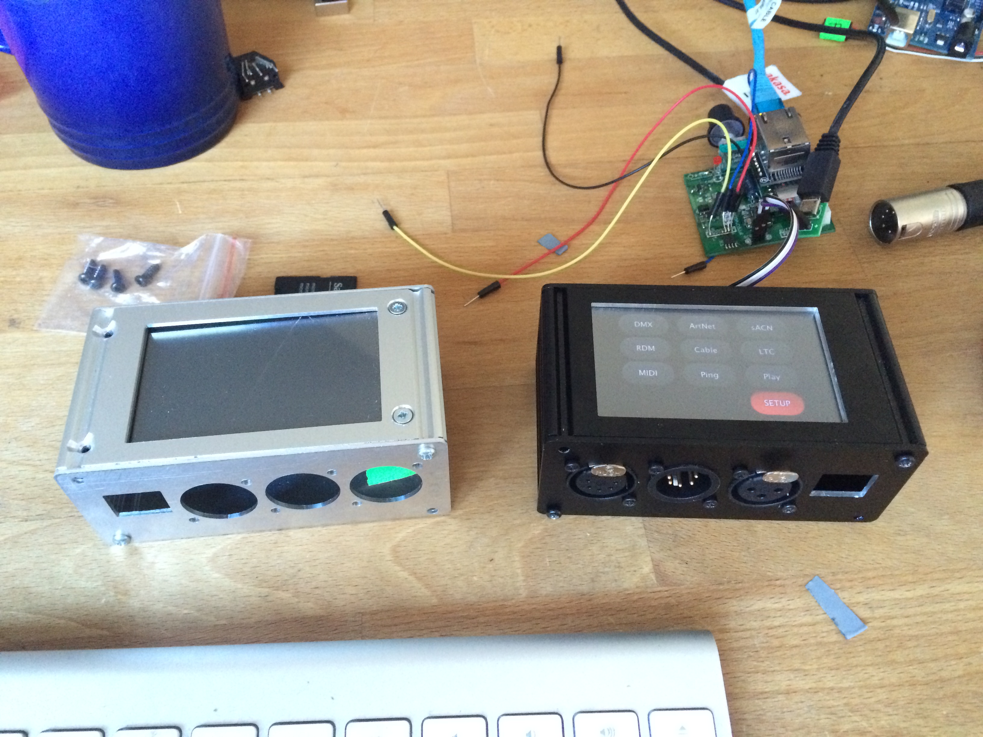
So some of you know I have been working on a new tester. It is not going to replace the STATE, it is quite a different beast and serves a smaller subset of people I think. It is probably about time that I talked about it though, as I need some push to get it to a version that I can actually give to people to try out.
This prototype is currently being held up in hardware… and software… If anyone is in a position to get on board with some software I would be interested in talking. Maybe open source the whole project ? I would love to be able to make the boxes for other people to develop amazing software for.
Its based on a Teensy (because I love them) and because it reduces the hassle of prototyping with a really good capable processor.
Now follows a really long list, the colours are ORANGE for nearly there, needs work or has some obvious problems, GREEN for all good, first round tests ok. RED is not even started, don’t go there, hiding in a corner from the problem.
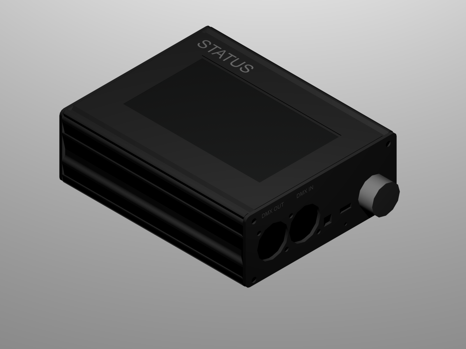
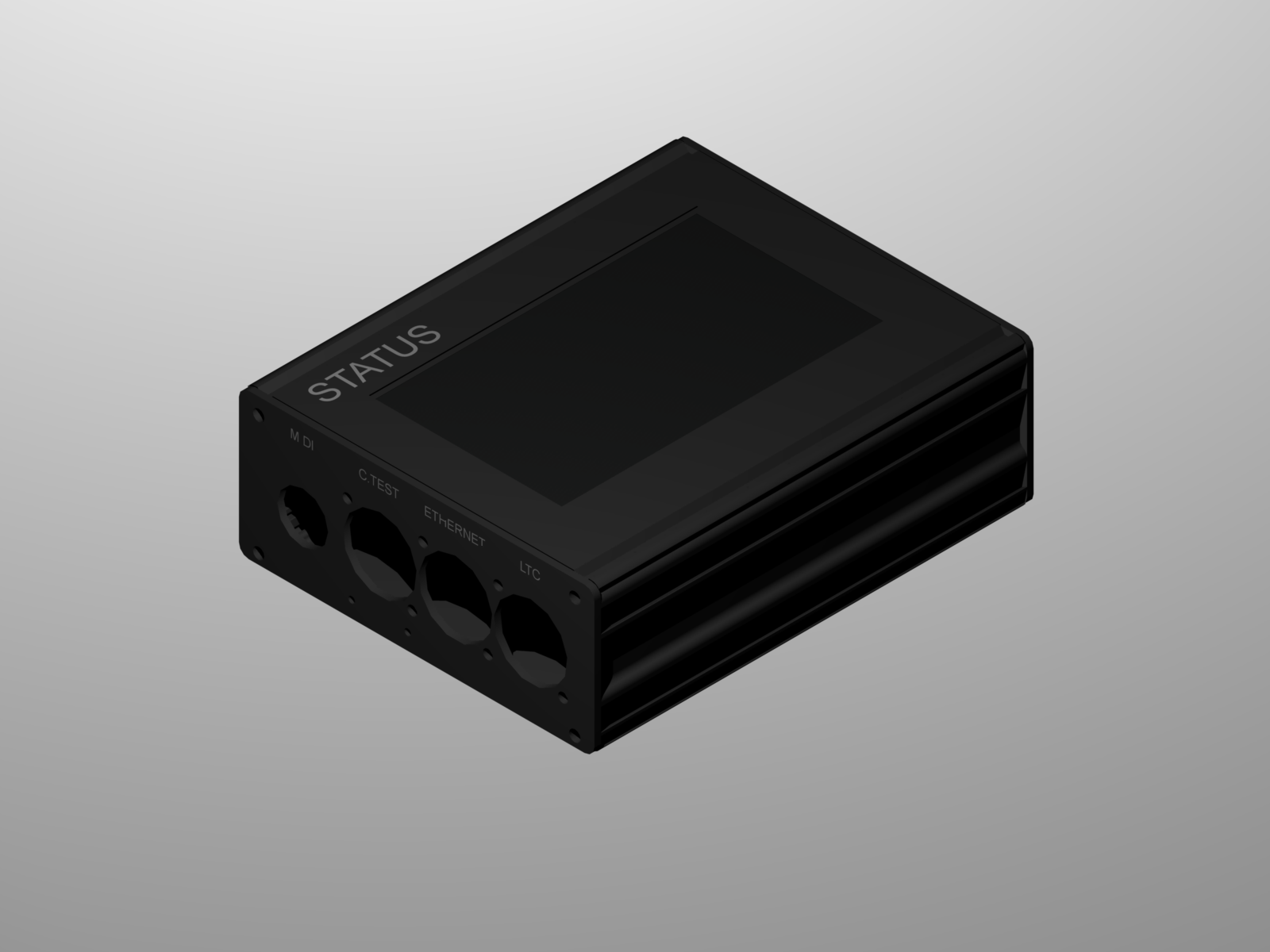
STATUS – Lighting protocols tester
Specification
STATUS is a multipurpose tool aimed at the live events industry. It allows a field technician to diagnose faults, test for presence
of correct signals and wiring and control lighting equipment across a variety of different control protocols.
The unit can be used to act as a protocol bridge in some circumstances, and data can be recorded and played back from a micro SD card.
DMX, DMX RDM, ArtNET, sACN, OSC, MIDI, MTC, LTC and supported at this time.
The battery powered tester frees the technician from carrying around a easily damaged expensive laptop and multiple dongles.
The unit also provides a computer interface for the mentioned protocols, and a suit of applications using the data will be avaiable soon. One, the LTC display is already available – Allowing the display of SMPTE Timecode on a Mac or PC in a floating window, so values can be embedded with screen recordings, or used as a large clock readout.
DMX
The unit can receive and transmit DMX512, STATES can be set up by channel or individual fixtures can be tested from on board library (updated via micro SD card included)
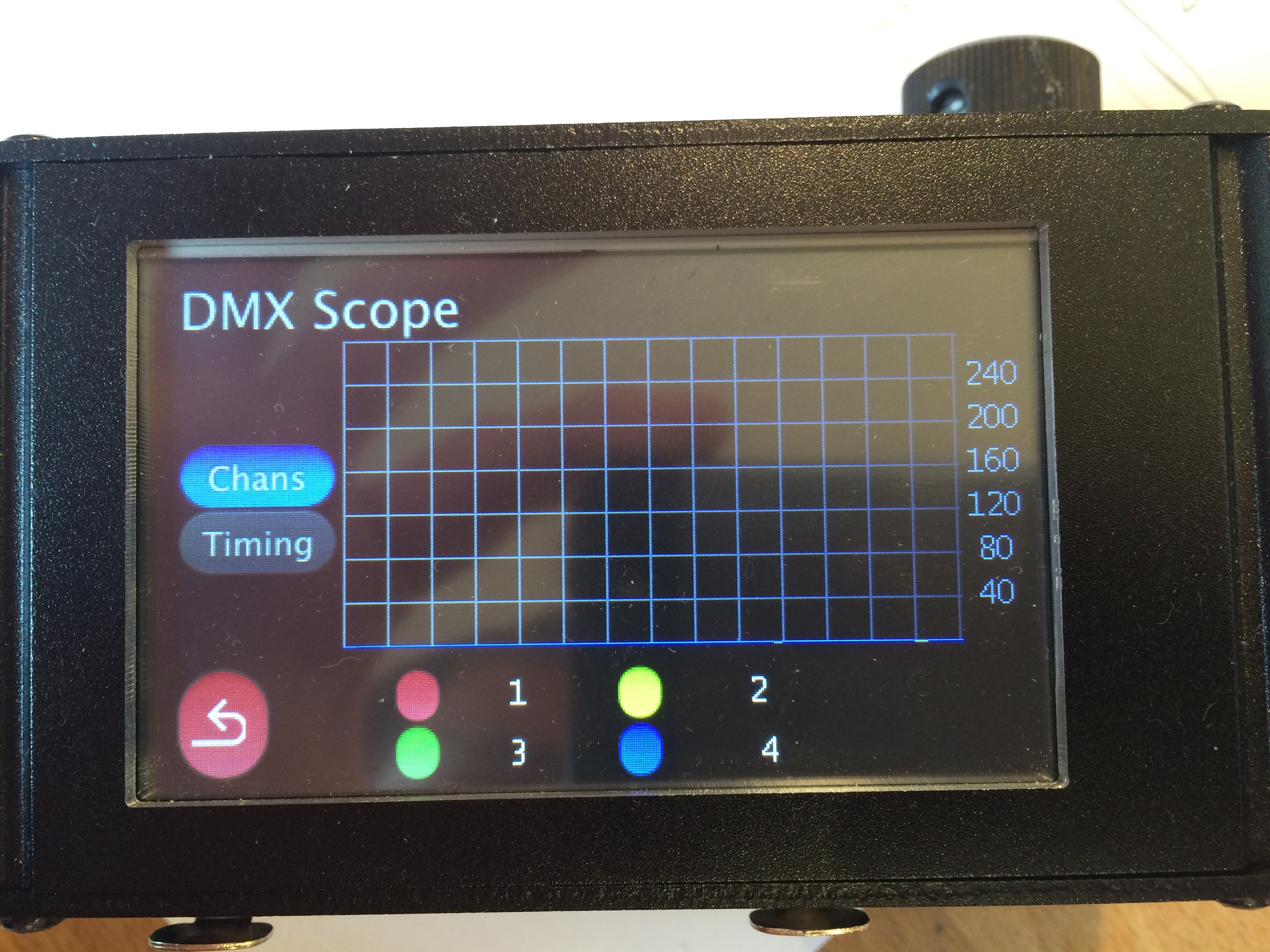
Scope mode; 4 channels can be views level against time on an oscilloscope style display. – helpful for diagnosing transient faults.
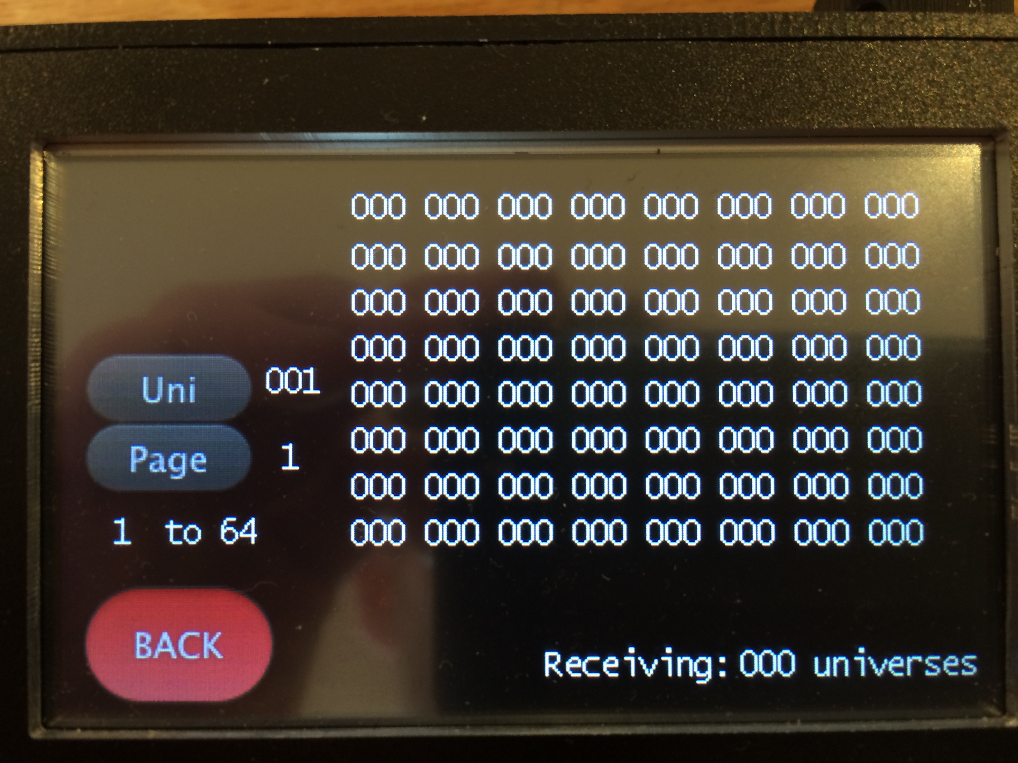
64 channel levels viewable at once in DMX input view
Completed states can be saved to SD card for replay via DMX or any other below protocol.
Open and short circuits can be detected in standard wired DMX 5pin XLR cable (pins 1,2,3)
Pictorial reference for ease of diagnosis.
New board has broken this…
ArtNet
All features of DMX
Stat page showing universes on network, framerate etc
Send to any Universe, by channel or fixture.
Save a Universe to memory (SD card) or All incoming universes to a memory. (selectable)
sACN (E131)
As per ArtNet features
Send
receive
port to other protocols?
OSC
receive and display incoming strings on a fixed port.
send test string
MIDI
Input log, shows incoming data on inbult 5pin DIN connector
MSC decode, decodes MSC into human readable Cue numbers etc
Midi output to send notes on/pff, pitch and velocity changes.
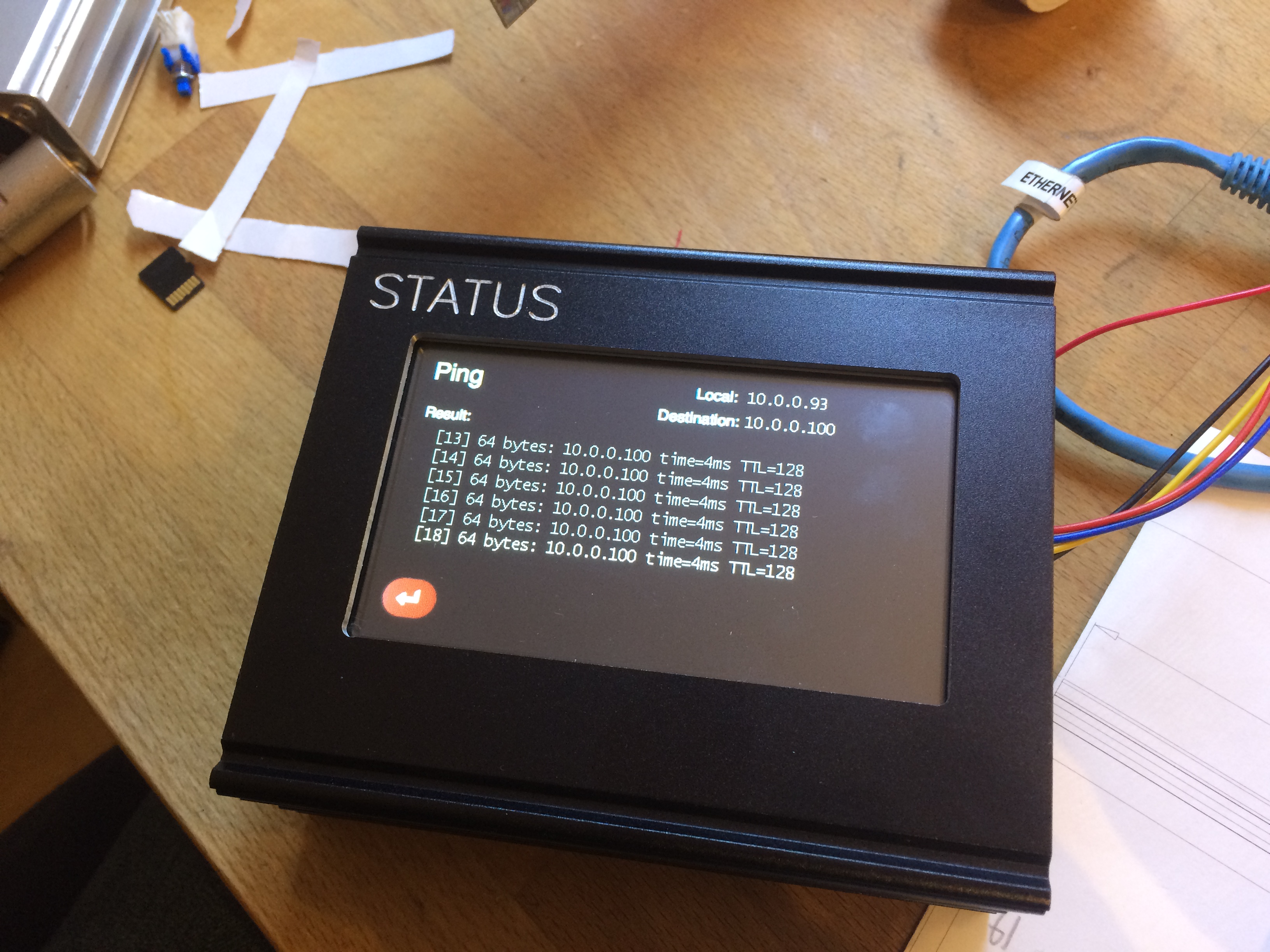
Ping
Ping a device on the local network. Selectable “to” and “from” IP addresses
MTC
Display Midi timecode and frame rate
LTC
Display SMPTE Linear Timecode (LTC) and frame rate from inbuilt 3pin XLR
Display average incoming signal level in mV and on bargraph
MAC and PC App to display LTC in a floating window (for screen recordings, TC tagging, larger clock displays etc) – Done
PLAYBACK
Playback saved memories to DMX, ArtNet and sACN. Regardless of where they came from.
Memories can be edited easilyfrom the SD card in a text editor or VIA SOME SOFTWARE PRODUCT..??
Debug
The USB on the device outputs serial which can be viewed in any terminal program, providing an ALL PROTOCOLS to serial adaptor for logging projects etc.
Could be used to timestamp with LTC for example, or view incoming MSC comands over the course of a day.
HARDWEAR
Encoder for rapid level setting (clickable to jump 0,50,100%), encoder also selects universes etc.
Touchscreen
Rechargeable Lithium Polymer battery, charges via micro usb B, using supplied cable.
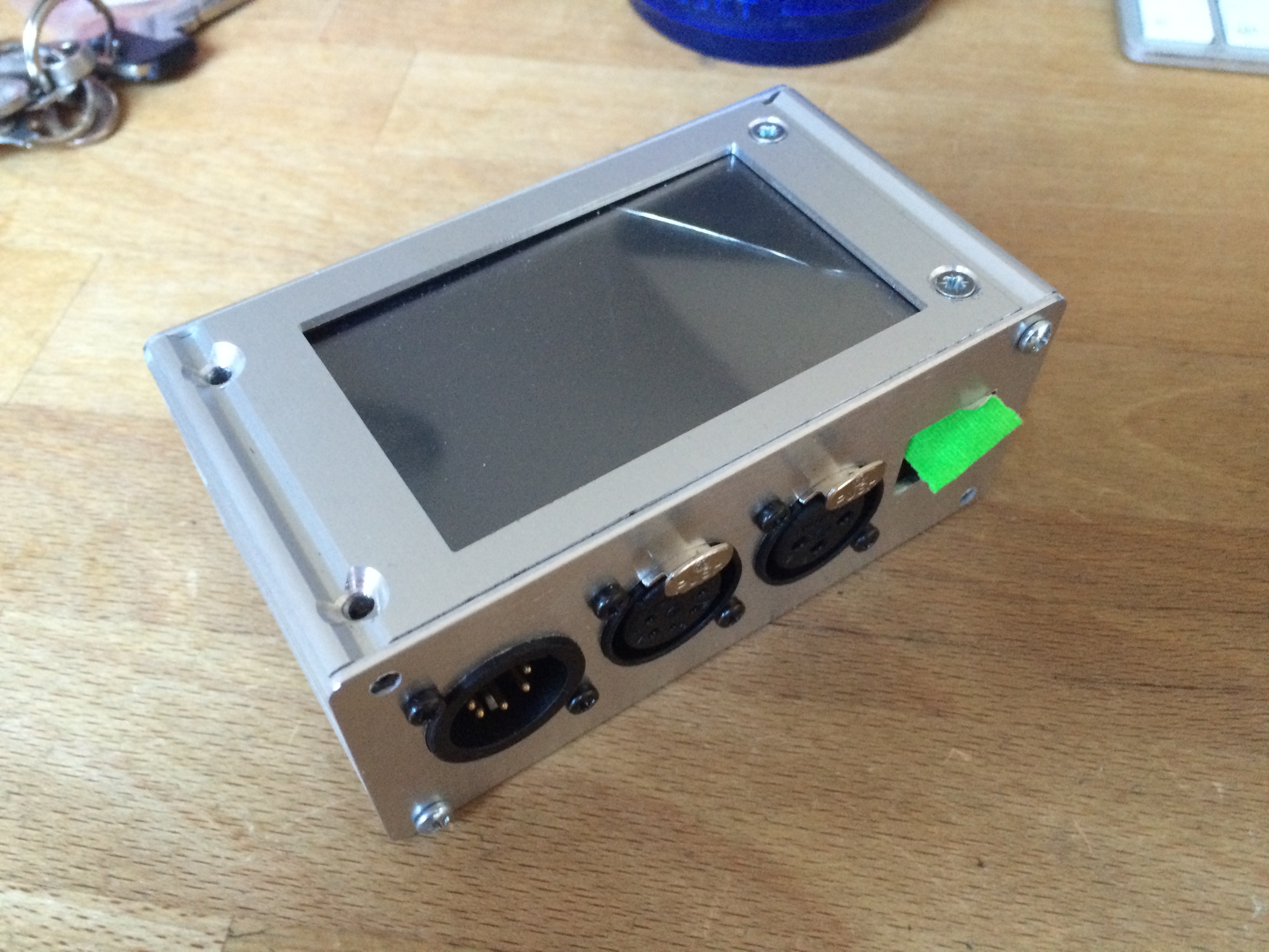
Robust extruded aluminium case
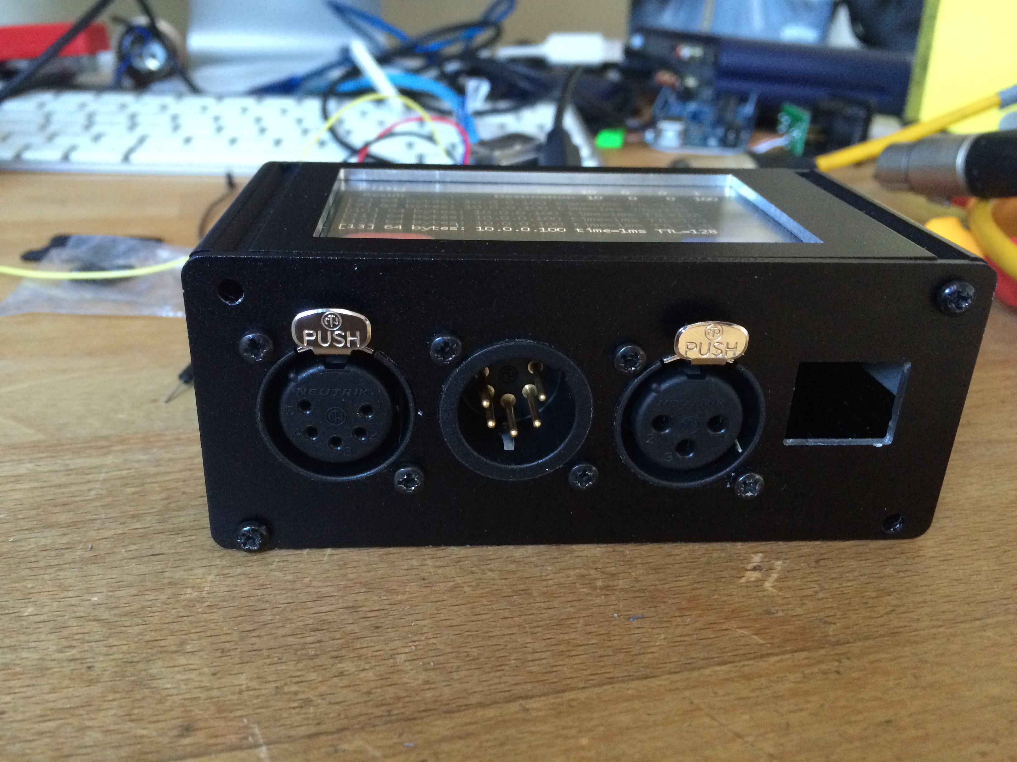
XLR 5 pin Male DMX
XLR 5 Pin Female DMX
XLR 3 Pin Female (LTC)
DIN 5pin (MIDI)
RJ45 Socket (ArtNet,sACN,Ping,OSC)
MicroSD – fixture library and saved states – editiable via any text editor.

 A few months ago I did a rush job to detect some footballs in very small football nets for a football boot brand, the player had to boot the ball into small holes in a wall in sequence to win. I got this working with one of my “BEAM” boxes, but modified to accept 12 laser beam break sensors, so that a invisible net could be formed just behind the hole.
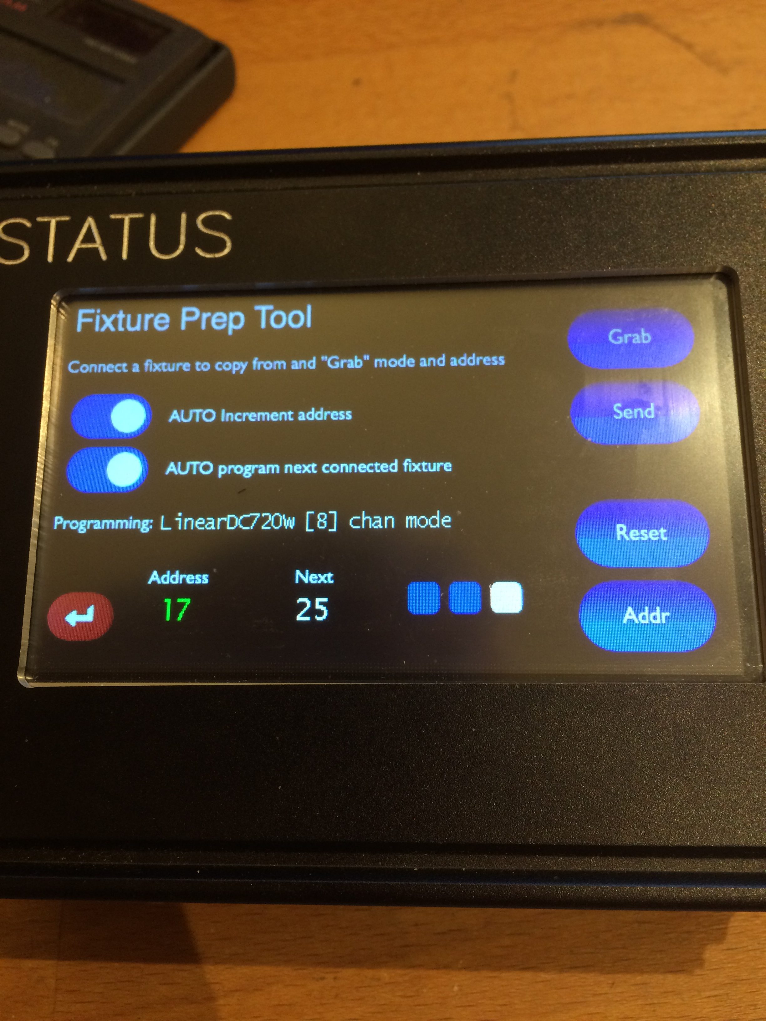
 The CNC machine has had a coolant upgrade. I was having to constantly squirt WD40 onto the end mills when cutting metals, which is both a pain in the ass and probably an environmental disaster, not to mention breathing in hot WD40 fumes is I’m sure not going to increase my life span.
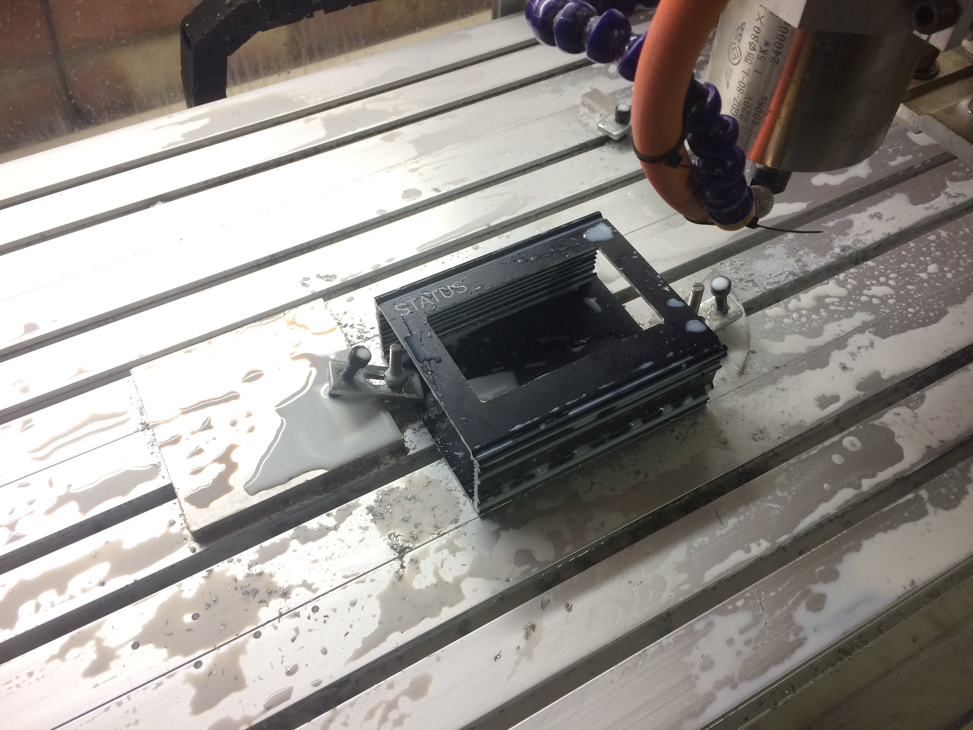
 Cue nearly a whole day of messing about trying to actually listen to that data.